
Which of the following statements about title block is/are true? Statement 1: The title block is situated in the bottom right-hand corner of the drawing sheet. Statement 2: The contents of the title block are standardised and cannot be modified to suit individual company needs.
Statement 1 is true, but statement 2 is false
The correct answer is that Statement 1 is true, but Statement 2 is false.
Statement 1: The title block is situated in the bottom right-hand corner of the drawing sheet. This statement is generally true. While there might be minor variations depending on the specific drafting standards followed (like ISO, ANSI, etc.), the title block is conventionally placed in the bottom right corner of engineering drawings. This placement is for consistency and easy identification of the drawing's key information.
Statement 2: The contents of the title block are standardized and cannot be modified to suit individual company needs. This statement is false. While there are standard elements commonly included in a title block (like drawing number, revision number, date, scale, project name, company name, and designer's initials), the specific content and format can be modified to suit an individual company's needs and requirements. Companies often customize their title blocks to reflect their branding and internal processes. For example, a company might add fields for specific project codes or internal identifiers not found in a generic standard.
Therefore, only Statement 1 is generally accurate regarding the typical placement of a title block.
Similar Questions
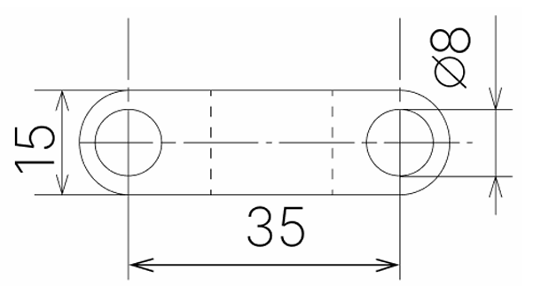
What type of view is represented of the given machine component?
When creating 10 mm single-stroke capital letters in vertical style, what does the 10 mm distance between horizontal parallel lines represent?
Match the following types of lines with their correct descriptions according to their orientation and characteristics. Description A. A line that is neither parallel to a horizontal plane nor perpendicular to it. B. A line that is perpendicular to horizontal lines. C. A line that changes its direction continuously. D. A line that is parallel to a horizontal plane.
Which type of line is used to represent hidden edges or surfaces in a technical drawing, as per BIS SP 46-2003?
Match the following, according to lettering and numbering (uppercase lettering) as per
BIS SP: 46-2003.
Width (W) Capital letters
(A) 5 (I) W
(B) 6 (II) A, M, Q, V, X, Y
(C) 7 (III) B, D, G, H, K, N, O, P, R, S, T, U and Z
(D) 9 (IV) C, E, F, LA statement and conclusion for pictorial drawing are given below. Determine the logical relationship between them.
Statement: Pictorial drawings are three-dimensional and provide a visual representation of an object.
Conclusion: Therefore, pictorial drawings are useful for describing the shape of a piece part or component.Which of the following statements is/are true about Non-Functional Dimensions (NF) in engineering drawing?
Statement 1: Non-functional Dimensions are shown without limits, as they do not affect the functionality of the component or space.
Statement 2: Non-Functional Dimensions are typically used for reference purposes only, and do not impact the assembly or performance of the component or space.Match the following designations of sheets with their respective trimmed sizes in length and breadth.
Designation Trimmed Size
A) A0 P) 297 × 420
B) A1 Q) 420 × 594
C) A2 R) 594 × 841
D) A3 S) 841 × 1189engineering drawings recommend(s) 20 mm wide margins for sheet sizes AO and A1 in
In a project involving the design of a pipeline for a building, which technical drawings would need to be referenced together?
Important Questions from Engineering Drawing
What is a polygon with 12 sides called?
Wiring diagrams, circuit diagrams and electrical installation drawings are examples of which of the following types of engineering drawings?
Which of the following is NOT an element of dimensioning ?
Which of the following drawing instruments is used to draw smooth curves/arcs?
_______ is a dimension that is essential to the functioning of the component or space that is generally shown with limits.



