
Which of the following circuits cannot be used to measure the resistance of resistor R?
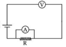
Measuring Resistance Using Different Circuits
To measure the resistance of a resistor, common methods involve using instruments like ammeters and voltmeters, or specialized circuits like the Wheatstone bridge. The ammeter measures the current flowing through the resistor, and the voltmeter measures the voltage across it. By applying Ohm's Law, \( R = \frac{V}{I} \), the resistance can be calculated.
Analyzing Different Circuit Configurations for Resistance Measurement
Let's examine each circuit provided in the options to determine if it can be used to measure the resistance of resistor R.
Circuit 1 (Option 1)
This circuit shows an ammeter connected in series with the resistor R, and a voltmeter connected in parallel across the resistor R. In this configuration, the ammeter measures the current (I) flowing through R, and the voltmeter measures the voltage (V) dropped across R. Using Ohm's law, the resistance R can be calculated as \( R = \frac{V}{I} \). This is a standard method for measuring resistance.
Circuit 2 (Option 2)
In this circuit, the ammeter is connected in series with resistor R. However, the voltmeter is connected in parallel across both the ammeter and the resistor R. This means the voltmeter measures the total voltage drop across the series combination of the ammeter (which has its own internal resistance, let's call it \( R_A \)) and the resistor R. The current measured by the ammeter is I. The voltage measured by the voltmeter is \( V_{total} = I \times (R_A + R) \). If we calculate \( \frac{V_{total}}{I} \), we get \( R_A + R \). This value is not the resistance of R alone unless the ammeter's resistance \( R_A \) is negligible or known and subtracted, which is generally not assumed for a simple measurement setup without calibration. Therefore, this circuit configuration cannot directly measure the resistance of R accurately.
Circuit 3 (Option 3)
This circuit represents a Wheatstone bridge. A Wheatstone bridge is a comparison circuit used for measuring an unknown electrical resistance by balancing two legs of a bridge circuit, one leg of which includes the unknown component. When the bridge is balanced (the galvanometer shows zero current), the ratio of resistances in the known legs is equal to the ratio of resistances in the unknown leg and its adjacent known leg. The resistance of R can be determined using this balance condition. This is a very common and often precise method for measuring resistance.
Circuit 4 (Option 4)
This circuit is identical to Circuit 1. It shows an ammeter in series with R and a voltmeter in parallel across R. As explained for Circuit 1, this is a standard and valid method for measuring the resistance of R using Ohm's law \( R = \frac{V}{I} \).
Based on the analysis, Circuit 2 is the only one that does not provide a direct measurement of the resistance of R using the ratio of the measured voltage and current, due to the voltmeter measuring the voltage drop across both the ammeter and R.
Therefore, the circuit that cannot be used to measure the resistance of resistor R is the one depicted in Option 2.
| Circuit (Option) | Configuration | Measurement Capability for R | Reason |
|---|---|---|---|
| 1 | Ammeter in series with R, Voltmeter across R | Yes | Measures V across R and I through R; \( R = V/I \) |
| 2 | Ammeter in series with R, Voltmeter across Ammeter + R | No (Directly) | Measures V across \( R_A + R \); ratio gives \( R_A + R \) |
| 3 | Wheatstone Bridge | Yes | Compares unknown R with known resistances to achieve balance |
| 4 | Ammeter in series with R, Voltmeter across R | Yes | Measures V across R and I through R; \( R = V/I \) |
Revision Table: Understanding Resistance Measurement
- Ammeter-Voltmeter Method: Measures current through and voltage across a component to calculate resistance using Ohm's law.
- Correct Ammeter-Voltmeter Connections: Ammeter in series with the component, Voltmeter in parallel across the component.
- Wheatstone Bridge: A precise method comparing an unknown resistance with known values to achieve a balanced state.
- Incorrect Connections: Voltmeter placed to measure voltage across multiple components in series (like ammeter + resistor) leads to measuring the total resistance of the combination, not just the target resistor.
Additional Information: Ideal vs. Real Meters
In practical scenarios, ammeters and voltmeters are not ideal. An ideal ammeter has zero internal resistance, and an ideal voltmeter has infinite internal resistance. However, real ammeters have a small internal resistance (\( R_A \)), and real voltmeters have a large, but finite, internal resistance (\( R_V \)).
The ammeter-voltmeter method has two common configurations:
- Voltmeter across R (as in Circuits 1 & 4): This method measures the correct voltage across R but the ammeter measures the current through R. Error arises because the voltmeter draws some current if its resistance \( R_V \) is not infinite. This configuration is better for measuring low resistances.
- Voltmeter across Ammeter + R (as in Circuit 2): This method measures the correct current through R (and the ammeter), but the voltmeter measures the total voltage across the series combination of the ammeter and R. Error arises because the ammeter has resistance \( R_A \). This configuration is better for measuring high resistances, where \( R_A \) is negligible compared to R.
Circuit 2 in the question is problematic because the voltmeter measures \( V = I(R_A + R) \). While this ratio gives \( R_A + R \), it does not directly give R, making it unsuitable for a simple measurement of R unless \( R_A \) is negligible compared to R or its value is known. Circuit 1 and 4 correctly isolate the voltage measurement across R.
Important Questions from Current Electricity
Figure shows drift speed Vd of conduction electrons in a copper wire versus position (X) for the three sections. Then,
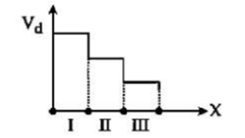
A. Radius of III > Radius of II > Radius of I
B. Electric Field in III > Electric Field in II > Electric Field in I
C. Radius of wire is same in all sections
D. Conductivity is same in all sections
Choose the correct answer from the options given below:
The temperature at which the resistance of a conductor becomes 30% more than that of its resistance at 47°C will be:
(Given the value of the temperature coefficient of resistance of the conductor is 2 × 10⁻⁴ K-1.)
Cell having an emf E and internal resistance r is connected across a variable external resistance R. As the resistance R is increased, the plot of potential difference V across R is given by:
In the potentiometer circuit, the balance point is at X. The balance point will be shifted right towards B when:
A. Resistance R is increased keeping all other parameters constant
B. Resistance S is increased keeping all other parameters constant
C. Cell P is replaced by another cell whose emf is lower than Q
D. The polarity of Q is reversed
Choose the correct answer from the options given below:
Kirchhoff’s First Law, ∑ I = 0 at a junction deals with conservation of:


