
In the potentiometer circuit, the balance point is at X. The balance point will be shifted right towards B when: A. Resistance R is increased keeping all other parameters constant B. Resistance S is increased keeping all other parameters constant C. Cell P is replaced by another cell whose emf is lower than Q D. The polarity of Q is reversed Choose the correct answer from the options given below:
(A), (B) only
In a potentiometer circuit, the balance point is determined by the potential gradient along the wire.
- Increasing R: This increases the total resistance of the primary circuit, reducing the current and thereby increasing the potential gradient. As a result, the balance point shifts towards B.
- Increasing S: This increases the resistance in the secondary circuit, reducing the current drawn by the cell, thereby increasing the balance length. This also shifts the balance point towards B.
- Replacing P with a lower emf cell (Option C): This would shift the balance point left, not right.
- Reversing polarity (Option D): This would nullify the balance condition, not shift the balance point.
Thus, the correct answer is (c) (A) and (B) only.
Important Questions from Current Electricity
Figure shows drift speed Vd of conduction electrons in a copper wire versus position (X) for the three sections. Then,
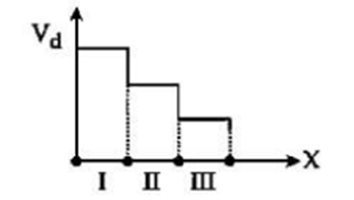
A. Radius of III > Radius of II > Radius of I
B. Electric Field in III > Electric Field in II > Electric Field in I
C. Radius of wire is same in all sections
D. Conductivity is same in all sections
Choose the correct answer from the options given below:
Which of the following circuits cannot be used to measure the resistance of resistor R?
The temperature at which the resistance of a conductor becomes 30% more than that of its resistance at 47°C will be:
(Given the value of the temperature coefficient of resistance of the conductor is 2 × 10⁻⁴ K-1.)
Cell having an emf E and internal resistance r is connected across a variable external resistance R. As the resistance R is increased, the plot of potential difference V across R is given by:
Kirchhoff’s First Law, ∑ I = 0 at a junction deals with conservation of:


