
What does the symbol given below denote in a circuit diagram?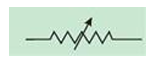
Variable resistor
The symbol shown in the image denotes a variable resistor in a circuit diagram.
A variable resistor, also known as a potentiometer or rheostat, allows for the adjustment of electrical resistance within a circuit. The arrow within the symbol indicates the adjustable nature of the resistance. Unlike a fixed resistor represented by a simple zig-zag line, this symbol clearly shows a mechanism for changing the resistance value.
Let's look at why the other options are incorrect:
- Voltmeter: A voltmeter is represented by a circle with a 'V' inside, indicating a device for measuring voltage.
- Voltage source: A voltage source is typically depicted as a circle with a '+' and '-' symbol to denote the positive and negative terminals.
- Resistor: A fixed resistor is usually represented by a zig-zag line. The symbol in the image shows a modification of this to indicate adjustable resistance.
Therefore, the correct answer is a variable resistor because the image clearly displays the characteristic symbol used to represent a component with adjustable resistance in electrical circuit diagrams.
Similar Questions
According to the ISO-A size series, what is the designation of a trimmed sheet with dimensions 297 mm × 420 mm?
Which of the following noise levels is considered potentially harmful to human health if experienced over extended periods?
Which of the following statements is/are true about Functional Dimensions (F) in engineering drawing?
Statement 1: Functional Dimensions are essential to the function of the component or space.
Statement 2: Functional Dimensions are typically shown without limits.
Statement 3: Functional Dimensions are only shown for reference purposes.A cube with a mass of 5.74 g occupies a volume of 1.2 cm³. The density (in g/cm³) expressed with the correct number of significant figures is ______.
According to BIS SP 46-2003, which of the following applications is correctly represented by a chain-thin line in engineering drawings?
Use of energy-efficient machineries in industrial settings primarily helps ______.
An ammeter has 20 divisions between 0 A and 2 A. The least count of ammeter is
Match the columns:
Engineering Applications Type of Engineering Drawings
A) Plan, front elevation of homes to be built, foundation drawings
P) Mechanical Engineering Drawings
B) Circuit diagrams and Electrical installation drawings
Q) Electronics Engineering drawings
C) PCB tracks drawings
R) Electrical Engineering drawings
D) Riveted joints and Welded joints
S) Civil Engineering drawingsWhich of the following is true?
Which of the following statements is/are true?
Statement 1: Heat conductors allow heat to pass through them easily.
Statement 2: All plastics are good conductors of heat.
Important Questions from Miscellaneous - Physics
The force which makes a vehicle to stop when brake is applied is called __________.
According to the ISO-A size series, what is the designation of a trimmed sheet with dimensions 297 mm × 420 mm?
- What does PCB stand for in electric circuits?
Which of the following noise levels is considered potentially harmful to human health if experienced over extended periods?
Which physicist was famous for the gold foil experiment?



