
In an AC circuit, the current leads the voltage by π/2. The circuit is:
Purely capacitive
Understanding Phase Relationship in AC Circuits
In alternating current (AC) circuits, the voltage and current do not always reach their peak values at the same time. The difference in time between the voltage peak and the current peak is represented as a phase difference. This phase difference depends on the type of components present in the circuit.
Phase Relationships for Different AC Circuit Elements
- Purely Resistive Circuit: In a circuit containing only resistance (R), the current and voltage are in phase. This means they reach their maximum and minimum values at the same time. The phase difference is 0 degrees or 0 radians.
- Purely Inductive Circuit: In a circuit containing only inductance (L), the voltage leads the current by a phase angle of $\pi/2$ radians (or 90 degrees). Alternatively, we can say the current lags the voltage by $\pi/2$.
- Purely Capacitive Circuit: In a circuit containing only capacitance (C), the current leads the voltage by a phase angle of $\pi/2$ radians (or 90 degrees). Alternatively, we can say the voltage lags the current by $\pi/2$.
Analyzing the Given Condition: Current Leads Voltage by π/2
The question states that in the given AC circuit, the current leads the voltage by $\pi/2$. Let's compare this condition with the phase relationships described above:
- Purely resistive circuit: Current is in phase with voltage (0 phase difference). This does not match the condition.
- Purely inductive circuit: Current lags voltage by $\pi/2$. This does not match the condition (the opposite is true).
- Purely capacitive circuit: Current leads voltage by $\pi/2$. This exactly matches the condition given in the question.
Therefore, a circuit where the current leads the voltage by $\pi/2$ must be a purely capacitive circuit.
| Circuit Type | Phase Relationship (Voltage vs. Current) |
|---|---|
| Purely Resistive | Voltage and current are in phase ($\phi = 0$) |
| Purely Inductive | Voltage leads current by $\pi/2$ |
| Purely Capacitive | Current leads voltage by $\pi/2$ |
Based on the analysis of phase relationships, the circuit where the current leads the voltage by $\pi/2$ is a purely capacitive circuit.
Revision Table: Key AC Circuit Concepts
| Component | Reactance/Resistance | Phase Angle ($\phi$) | Impedance (Z) |
|---|---|---|---|
| Resistor (R) | Resistance R | 0 (Voltage & Current in phase) | $Z = R$ |
| Inductor (L) | Inductive Reactance $X_L = \omega L$ | +$\pi/2$ (Voltage leads current) | $Z = j X_L = j \omega L$ |
| Capacitor (C) | Capacitive Reactance $X_C = \frac{1}{\omega C}$ | -$\pi/2$ (Current leads voltage) | $Z = -j X_C = \frac{1}{j \omega C}$ |
Additional Information: Impedance and Phase Angle
In AC circuits, the opposition to current flow is called impedance (Z). Impedance is a complex quantity that includes both resistance and reactance (opposition from inductors and capacitors). The phase difference ($\phi$) between the total voltage across the circuit and the total current through the circuit is determined by the circuit's impedance.
For a general series RLC circuit, the impedance is given by $Z = R + j(X_L - X_C)$. The phase angle $\phi$ is given by $\tan \phi = \frac{X_L - X_C}{R}$.
- If the circuit is purely resistive ($L=0, C=0$), then $X_L = 0$ and $X_C = 0$. $Z = R$, $\tan \phi = \frac{0}{R} = 0$. $\phi = 0$. Voltage and current are in phase.
- If the circuit is purely inductive ($R=0, C=0$), then $X_C = 0$. $Z = j X_L$. $\tan \phi = \frac{X_L}{0} = \infty$. $\phi = +\pi/2$. Voltage leads current.
- If the circuit is purely capacitive ($R=0, L=0$), then $X_L = 0$. $Z = -j X_C$. $\tan \phi = \frac{-X_C}{0} = -\infty$. $\phi = -\pi/2$. Voltage lags current, which is equivalent to current leading voltage by $\pi/2$.
This detailed analysis of impedance and phase angle further confirms that a current leading the voltage by $\pi/2$ is characteristic of a purely capacitive circuit.
Purely capacitive
AC Circuit Analysis: Phase Relationship (Complex Impedance Approach)
The problem requires identifying the AC circuit where the current (\( I \)) leads the voltage (\( V \)) by \( \pi/2 \). We will use the method of complex impedance to solve this.
Step-by-Step Solution using Complex Impedance:
- Represent Voltage and Current as Phasors:
In AC circuit analysis using complex numbers, sinusoidal voltages and currents at a steady angular frequency \( \omega \) are represented as phasors (complex numbers). \[ \mathbf{V} = V_{rms} e^{j\phi_V} \] \[ \mathbf{I} = I_{rms} e^{j\phi_I} \] Here, \( V_{rms} \) and \( I_{rms} \) are the root-mean-square amplitudes, \( \phi_V \) and \( \phi_I \) are their phase angles, and \( j \) is the imaginary unit (\( j^2 = -1 \)). - Define Complex Impedance (\( \mathbf{Z} \)):
Complex impedance \( \mathbf{Z} \) is defined as the ratio of the voltage phasor to the current phasor: \[ \mathbf{Z} = \frac{\mathbf{V}}{\mathbf{I}} \] Substituting the phasor forms: \[ \mathbf{Z} = \frac{V_{rms} e^{j\phi_V}}{I_{rms} e^{j\phi_I}} = \left(\frac{V_{rms}}{I_{rms}}\right) e^{j(\phi_V - \phi_I)} \] The magnitude of the impedance is \( |\mathbf{Z}| = V_{rms} / I_{rms} \), and the angle (argument) of the impedance is: \[ \arg(\mathbf{Z}) = \phi = \phi_V - \phi_I \] This angle \( \phi \) is the phase difference between voltage and current. - Interpret the Given Condition in Terms of \( \phi \):
The problem states that "current leads the voltage by \( \pi/2 \)". This means: \[ \phi_I - \phi_V = \frac{\pi}{2} \] Therefore, the phase angle \( \phi \) as defined by the impedance argument is: \[ \phi = \phi_V - \phi_I = -\frac{\pi}{2} \] We are looking for a circuit component whose complex impedance \( \mathbf{Z} \) has an angle of \( -\pi/2 \). - Determine the Complex Impedance of Basic Circuit Elements:
- Resistor (R): The voltage and current are in phase. \( \mathbf{V}_R = R \mathbf{I}_R \). \[ \mathbf{Z}_R = \frac{\mathbf{V}_R}{\mathbf{I}_R} = R \] Since R is a positive real number, its angle is \( \arg(\mathbf{Z}_R) = 0 \).
- Inductor (L): The voltage-current relationship is \( v_L = L \frac{di_L}{dt} \). In phasor form, this becomes \( \mathbf{V}_L = j\omega L \mathbf{I}_L \). \[ \mathbf{Z}_L = \frac{\mathbf{V}_L}{\mathbf{I}_L} = j\omega L \] Since \( \omega L \) is positive, \( \mathbf{Z}_L \) is a purely positive imaginary number. Its angle is \( \arg(\mathbf{Z}_L) = +\frac{\pi}{2} \).
- Capacitor (C): The voltage-current relationship is \( i_C = C \frac{dv_C}{dt} \). In phasor form, this becomes \( \mathbf{I}_C = j\omega C \mathbf{V}_C \). \[ \mathbf{Z}_C = \frac{\mathbf{V}_C}{\mathbf{I}_C} = \frac{1}{j\omega C} \] Since \( \frac{1}{j} = -j \), we have: \[ \mathbf{Z}_C = -j \left( \frac{1}{\omega C} \right) \] Since \( \frac{1}{\omega C} \) is positive, \( \mathbf{Z}_C \) is a purely negative imaginary number. Its angle is \( \arg(\mathbf{Z}_C) = -\frac{\pi}{2} \).
- Match the Required Impedance Angle:
We need a circuit where the impedance angle \( \phi = \arg(\mathbf{Z}) \) is \( -\pi/2 \). Comparing this with the results above:- Resistor: \( \arg(\mathbf{Z}_R) = 0 \) (No match)
- Inductor: \( \arg(\mathbf{Z}_L) = +\pi/2 \) (No match)
- Capacitor: \( \arg(\mathbf{Z}_C) = -\pi/2 \) (Match!)
- Consider Mixed Circuits (Briefly):
For circuits with combinations of R, L, C, the impedance is a complex number with both real and imaginary parts (unless at resonance where \(X_L=X_C\)). For example, an RC circuit has \( \mathbf{Z} = R + \frac{1}{j\omega C} = R - jX_C \). Its angle is \( \phi = \arctan(-X_C/R) \), which lies between 0 and \( -\pi/2 \) (exclusive of \( -\pi/2 \) unless R=0). Similarly, for RL or RLC circuits, the angle is generally not exactly \( \pm \pi/2 \) unless the resistive component is zero. The option "resistance equal to reactance" (\( R=X \)) leads to angles of \( \pm \pi/4 \), not \( \pm \pi/2 \).
Conclusion:
Using the complex impedance method, we found that the component whose impedance \( \mathbf{Z} \) has an angle of \( -\pi/2 \) is the capacitor. An impedance angle of \( -\pi/2 \) corresponds to the voltage lagging the current by \( \pi/2 \), or equivalently, the current leading the voltage by \( \pi/2 \).
Final Answer:
The circuit is: Purely capacitive
Purely capacitive
The correct answer is:
✅ Purely capacitive
Explanation:
In an AC circuit:
- Current leads voltage by π/2 (90°) → Purely capacitive circuit.
- Capacitors cause current to lead voltage due to their charge/discharge dynamics.
Key phase relationships:
- Purely resistive: Current and voltage are in phase (0° difference).
- Purely inductive: Current lags voltage by π/2.
- Resistance = Reactance: Phase difference is π/4 (45°).
Why Not Other Options?
- Purely resistive → No phase difference.
- R = X (Resistance = Reactance) → 45° phase shift (not 90°).
- Purely inductive → Current lags by 90° (opposite behavior).
Key Formula:
- Phase angle (θ) = tan⁻¹(Xₖ/R), where:
- Xₖ = Capacitive reactance (X꜀) or Inductive reactance (Xʟ).
- For pure capacitive: R = 0 → θ = 90° (current leads).
Answer: Purely capacitive (Option 4) ✅
Important Questions from Alternating Current
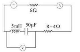
In the shown AC source, the voltage is given as V = 20 cos 2000t. Neglecting source resistance, the voltmeter and ammeter readings will be:
The same current is flowing in two AC circuits. The first circuit contains a pure inductor and the second, a capacitor. If the frequency of the AC is increased, then the current will:
A 25 μF capacitor, a 0.10 H inductor, and a 25 Ω resistor is connected in series with an AC source of emf ε = 310 sin 314t. What is the frequency of the AC source?
The same current is flowing in two AC circuits. The first circuit contains a pure inductor and the second, a capacitor. If the frequency of the AC is increased, then the current will:
A 25 μF capacitor, a 0.10 H inductor, and a 25 Ω resistor is connected in series with an AC source of emf ε = 310 sin 314t. What is the frequency of the AC source?


