
In a 2-input AND gate used as an enable control circuit, which logic signal must be applied to the enable input to allow pulses to pass through?
A constant logic HIGH (1) signal
An enable control circuit using a 2-input AND gate requires a specific logic signal applied at its enable input to function correctly. Let's explore the functionality and select the proper signal:
Understanding the AND Gate:
An AND gate is a digital logic gate that outputs a logic HIGH (1) only when all its inputs are also HIGH (1). Otherwise, the output remains LOW (0).
Enable Input in a Control Circuit:
In a control circuit, the AND gate can be used to allow or block signals from passing through based on the state of one of its inputs, typically referred to as the "enable" input.
Analyzing Signal Requirements:
- A high-impedance open circuit connection: This doesn't provide a logical HIGH or LOW value, making it unsuitable for guaranteeing consistent operation of the AND gate.
- An alternating signal that matches the pulse frequency exactly: This would require synchronizing with the pulses, making it complex and impractical for basic enabling functionality.
- A constant logic HIGH (1) signal: Applying a HIGH to the enable input means the gate allows incoming pulses to pass whenever they are HIGH. This ensures pulses pass through the gate.
- A constant logic LOW (0) signal: This would keep the gate output LOW (0) because the AND condition is never satisfied (one input is always 0).
Conclusion:
The correct logic signal to be applied to the enable input to allow pulses to pass through a 2-input AND gate is a constant logic HIGH (1) signal. This enables the gate to output the incoming signal (pulses) when they are HIGH.
Similar Questions
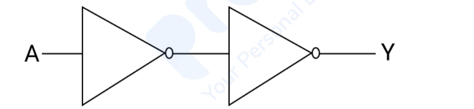
What is the output Y of the following digital circuit if the input A = 1?
(Note: Both the logic gates shown in the diagram are NOT gates.)
A 1 kHz square wave signal is applied to the input A of a NOT gate. What will be observed at the output of the NOT gate?
What is the decimal equivalent of the binary number 101101?
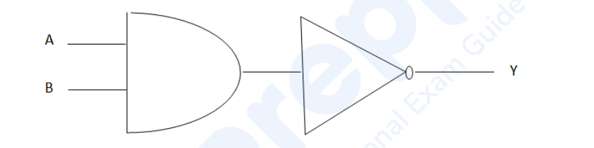
Consider the logic circuit shown in the given diagram. Which pair of the inputs A and B will produce output Y = 0?
During lab practice, if you connect the input of a NOT gate to a logic low (0), what practical output should you observe?
Which single logic gate can be used to implement the Boolean equation Y = A + B in a digital circuit?
Important Questions from Digital Electronics
Radix 2 is used for representing
First generation computers had which of the following?
How many flip flops is/are required for 10 state count in ripple counter?
Which of the following logic gate gives high output with all its inputs low
Latches are _______ circuits.



