
For the network given below:-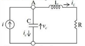
The state equation is:-
$\frac{d}{dt} \begin{bmatrix} V_c \\ i_L \end{bmatrix} = \begin{bmatrix} 0 & -\frac{1}{C} \\ \frac{1}{L} & -\frac{R}{L} \end{bmatrix} \begin{bmatrix} V_c \\ i_L \end{bmatrix} + \begin{bmatrix} \frac{1}{C} \\ 0 \end{bmatrix} i$
The given network is a simple RLC circuit. To derive the state-space equations, we need to express the circuit's dynamics in terms of its state variables. For this circuit, the state variables are:
- \(V_c\): the voltage across the capacitor.
- \(i_L\): the current through the inductor.
The state-space representation for an RLC circuit can be given by:
- \(\frac{dV_c}{dt} = \frac{1}{C}(i - i_L)\), which arises from the relationship \(i_c = C \frac{dV_c}{dt}\).
- \(\frac{di_L}{dt} = \frac{1}{L}(V_c - Ri_L)\), from the inductor's voltage-current relation.
Thus, using matrix notation, the state equations become:
| \(\frac{d}{dt} \begin{bmatrix} V_c \\ i_L \end{bmatrix} = \begin{bmatrix} 0 & -\frac{1}{C} \\ \frac{1}{L} & -\frac{R}{L} \end{bmatrix} \begin{bmatrix} V_c \\ i_L \end{bmatrix} + \begin{bmatrix} \frac{1}{C} \\ 0 \end{bmatrix} i\) |
This equation matches the given correct answer option:
\(\frac{d}{dt} \begin{bmatrix} V_c \\ i_L \end{bmatrix} = \begin{bmatrix} 0 & -\frac{1}{C} \\ \frac{1}{L} & -\frac{R}{L} \end{bmatrix} \begin{bmatrix} V_c \\ i_L \end{bmatrix} + \begin{bmatrix} \frac{1}{C} \\ 0 \end{bmatrix} i\)
This formulation reflects Kirchoff's laws for voltage and current in an RLC circuit, properly distinguishing between the effects of capacitance and inductance.
Important Questions from State Space Representation
A discrete system is represented by the difference equation
\(\left[ {\begin{array}{*{20}{c}} {{X_1}\left( {k + 1} \right)}\\ {{X_2}\left( {k + 1} \right)} \end{array}} \right] = \left[ {\begin{array}{*{20}{c}} a&{a - 1}\\ {a + 1}&a \end{array}} \right]\left[ {\begin{array}{*{20}{c}} {{X_1}\left( k \right)}\\ {{X_2}\left( k \right)} \end{array}} \right]\)
It has initial conditions X1(0) = 1; X2(0) = 0. The pole locations of the system for a = 1, areArrange the following in the sequence of steps for writing STATE EQUATION:-
A. Choose a normal tree for a network
B. Take either voltages or charges across the capacitor, which are tree branches and eithercurrents or fluxes through inductors, which are co-tree chords
C. Write independent KVL, KCL and branch voltage current relations (VCR).
D. Rearrange the vector matrix differential equation for state variable representation.
E. Eliminate all non-state variables of the network
Choose the correct answer from the options given below:- Consider the state-space representation of a system
$ \dot{x} = Ax + Bu $
where $x$ is the state vector, $u$ is the input, $A$ is the system matrix and $B$ is the input matrix. Choose the matrix $A$ from the following options such that the system has a pole at the origin. - The state and output equations for a control system are:
$$\dot{x} = \begin{bmatrix} -4 & -1.5 \\ 4 & 0 \end{bmatrix}x + \begin{bmatrix} 2 \\ 0 \end{bmatrix}u$$
$$y = \begin{bmatrix} 1.5 & 0.625 \end{bmatrix}x$$
Which of the following expressions correctly represents the transfer function $\frac{Y(s)}{U(s)}$ of the system with zero initial conditions? - The state-space model of a system is given as
$$ \begin{bmatrix} \dot{x}_1 \\ \dot{x}_2 \end{bmatrix} = \begin{bmatrix} 1 & 0 \\ 1 & 1 \end{bmatrix} \begin{bmatrix} x_1 \\ x_2 \end{bmatrix} + \begin{bmatrix} 1 \\ 1 \end{bmatrix} u(t) $$
where u(t) is a unit step input occurring at t = 0 and $x(0) = \begin{bmatrix} 1 \\ 0 \end{bmatrix}$.
The time response of the system is


