
Arrange the following in the sequence of steps for writing STATE EQUATION:-
A. Choose a normal tree for a network
B. Take either voltages or charges across the capacitor, which are tree branches and eithercurrents or fluxes through inductors, which are co-tree chords
C. Write independent KVL, KCL and branch voltage current relations (VCR).
D. Rearrange the vector matrix differential equation for state variable representation.
E. Eliminate all non-state variables of the network
Choose the correct answer from the options given below:
Understanding the Steps for Writing State Equations
Writing state equations is a fundamental process in analyzing the dynamic behavior of electrical networks. These equations form the basis of the state-space representation, which is widely used in control systems and circuit theory. The process involves systematically converting a network description into a set of first-order differential equations.
Detailed Breakdown of the Steps:
- A. Choose a normal tree for a network: This initial step involves applying graph theory concepts to the network. A 'tree' is a subgraph that connects all nodes of the network without forming any loops. Selecting a 'normal tree' simplifies the subsequent steps of formulating the state equations.
- B. Define State Variables: Once the tree is chosen, the state variables are identified. These are typically the minimum set of variables required to completely describe the system's state at any given time. For electrical networks, these are usually the voltages across capacitors (often associated with tree branches) and the currents through inductors (often associated with non-tree branches or 'chords'). The choice is often between voltages or charges for capacitors and currents or fluxes for inductors.
- C. Write Independent KVL, KCL, and VCR: This step involves applying Kirchhoff's laws and the component's voltage-current relationships (VCR). Independent Kirchhoff's Voltage Law (KVL) equations are written for the fundamental loops (related to chords), and independent Kirchhoff's Current Law (KCL) equations are written for the fundamental cut-sets (related to the tree branches). The VCRs for capacitors ($\textit{i} = C \frac{dv}{dt}$) and inductors ($\textit{v} = L \frac{di}{dt}$) are also formulated.
- E. Eliminate Non-State Variables: The equations derived in step C will contain both state variables (e.g., capacitor voltages, inductor currents) and non-state variables (e.g., inductor voltages, capacitor currents). This step focuses on eliminating these non-state variables by expressing them in terms of the state variables and their derivatives, using the VCRs established earlier.
- D. Rearrange for State Variable Representation: The final step is to consolidate and rearrange the derived equations into the standard state-space form. This results in a set of first-order differential equations, typically represented in matrix form as $\frac{dx(t)}{dt} = Ax(t) + Bu(t)$, where $x(t)$ is the state vector, $A$ is the system matrix, $B$ is the input matrix, and $u(t)$ is the input vector.
The Correct Sequence
To systematically derive the state equations, the steps must be performed in a specific logical order. Based on the standard procedure in network analysis:
- A. Choose a normal tree for a network
- B. Take either voltages or charges across the capacitor, which are tree branches and either currents or fluxes through inductors, which are co-tree chords
- C. Write independent KVL, KCL and branch voltage current relations (VCR)
- E. Eliminate all non-state variables of the network
- D. Rearrange the vector matrix differential equation for state variable representation
This sequence ensures that the network structure is properly defined, state variables are correctly identified, fundamental network laws are applied, intermediate variables are removed, and the final representation is achieved in the standard state-space form.
Important Questions from State Space Representation
A discrete system is represented by the difference equation
\(\left[ {\begin{array}{*{20}{c}} {{X_1}\left( {k + 1} \right)}\\ {{X_2}\left( {k + 1} \right)} \end{array}} \right] = \left[ {\begin{array}{*{20}{c}} a&{a - 1}\\ {a + 1}&a \end{array}} \right]\left[ {\begin{array}{*{20}{c}} {{X_1}\left( k \right)}\\ {{X_2}\left( k \right)} \end{array}} \right]\)
It has initial conditions X1(0) = 1; X2(0) = 0. The pole locations of the system for a = 1, areFor the network given below:-
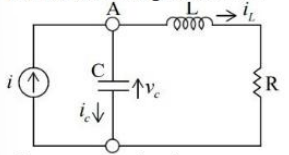
The state equation is:-- Consider the state-space representation of a system
$ \dot{x} = Ax + Bu $
where $x$ is the state vector, $u$ is the input, $A$ is the system matrix and $B$ is the input matrix. Choose the matrix $A$ from the following options such that the system has a pole at the origin. - The state and output equations for a control system are:
$$\dot{x} = \begin{bmatrix} -4 & -1.5 \\ 4 & 0 \end{bmatrix}x + \begin{bmatrix} 2 \\ 0 \end{bmatrix}u$$
$$y = \begin{bmatrix} 1.5 & 0.625 \end{bmatrix}x$$
Which of the following expressions correctly represents the transfer function $\frac{Y(s)}{U(s)}$ of the system with zero initial conditions? - The state-space model of a system is given as
$$ \begin{bmatrix} \dot{x}_1 \\ \dot{x}_2 \end{bmatrix} = \begin{bmatrix} 1 & 0 \\ 1 & 1 \end{bmatrix} \begin{bmatrix} x_1 \\ x_2 \end{bmatrix} + \begin{bmatrix} 1 \\ 1 \end{bmatrix} u(t) $$
where u(t) is a unit step input occurring at t = 0 and $x(0) = \begin{bmatrix} 1 \\ 0 \end{bmatrix}$.
The time response of the system is


