
An a.c voltage is applied to a resistor of resistance 5Ω and an inductor having inductive reactance of 5Ω connected in series. The phase difference between applied voltage and the current in the circuit is:
\( \frac{\pi}{4} \)
Understanding Phase Difference in AC R-L Series Circuits
In an alternating current (AC) circuit containing a resistor (R) and an inductor (L) connected in series, the applied voltage and the current generally do not oscillate in perfect synchronization. The difference in timing between the voltage and current waveforms is called the phase difference.
For a series R-L circuit, the impedance (Z) is the total opposition to current flow and depends on both the resistance (R) and the inductive reactance (\(X_L\)). The inductive reactance is the opposition offered by the inductor to the alternating current.
The phase difference (\(\phi\)) between the applied voltage across the series combination and the current flowing through the circuit is determined by the ratio of the inductive reactance to the resistance. This relationship is given by the formula:
\(\tan \phi = \frac{\text{Inductive Reactance}}{\text{Resistance}} = \frac{X_L}{R}\)
Calculating the Phase Difference
We are given the following values:
- Resistance, R = 5\(\Omega\)
- Inductive Reactance, \(X_L\) = 5\(\Omega\)
Now, we can substitute these values into the formula for the tangent of the phase difference:
\(\tan \phi = \frac{X_L}{R} = \frac{5 \, \Omega}{5 \, \Omega}\)
\(\tan \phi = 1\)
To find the phase difference \(\phi\), we need to find the angle whose tangent is 1. This is the arctangent (or inverse tangent) function:
\(\phi = \arctan(1)\)
In trigonometry, the angle whose tangent is 1 is \(\frac{\pi}{4}\) radians (or 45 degrees).
Therefore, the phase difference between the applied voltage and the current in the circuit is \(\frac{\pi}{4}\) radians.
In a series R-L circuit, the voltage leads the current, or equivalently, the current lags behind the voltage by this phase angle \(\phi\).
Summary of Calculation
Given:
- R = 5\(\Omega\)
- \(X_L\) = 5\(\Omega\)
Formula:
\(\tan \phi = \frac{X_L}{R}\)
Calculation:
\(\tan \phi = \frac{5}{5} = 1\)
\(\phi = \arctan(1) = \frac{\pi}{4}\)
Revision Table: AC Circuit Concepts
| Concept | Description | Formula (Series Circuit) |
|---|---|---|
| Resistance (R) | Opposition to AC/DC current flow by resistor. In phase with current. | R |
| Inductive Reactance (\(X_L\)) | Opposition to AC current flow by inductor. Voltage leads current by \(\frac{\pi}{2}\). | \(X_L = \omega L = 2\pi f L\) |
| Capacitive Reactance (\(X_C\)) | Opposition to AC current flow by capacitor. Voltage lags current by \(\frac{\pi}{2}\). | \(X_C = \frac{1}{\omega C} = \frac{1}{2\pi f C}\) |
| Impedance (Z) | Total opposition to AC current flow in a circuit containing R, L, C. | For R-L series: \(Z = \sqrt{R^2 + X_L^2}\) For R-C series: \(Z = \sqrt{R^2 + X_C^2}\) For R-L-C series: \(Z = \sqrt{R^2 + (X_L - X_C)^2}\) |
| Phase Difference (\(\phi\)) | Angle between applied voltage and total current. | For R-L series: \(\tan \phi = \frac{X_L}{R}\) For R-C series: \(\tan \phi = \frac{-X_C}{R}\) For R-L-C series: \(\tan \phi = \frac{X_L - X_C}{R}\) |
Additional Information: AC Circuit Analysis
Understanding phase difference is crucial in AC circuit analysis because it affects power calculations and circuit behavior. In a purely resistive AC circuit, the voltage and current are in phase (\(\phi = 0\)). In a purely inductive circuit, the voltage leads the current by \(\frac{\pi}{2}\) (\(\phi = +\frac{\pi}{2}\)). In a purely capacitive circuit, the voltage lags the current by \(\frac{\pi}{2}\) (\(\phi = -\frac{\pi}{2}\)).
When resistors, inductors, and capacitors are combined in series or parallel, the overall phase difference depends on the relative values of R, \(X_L\), and \(X_C\). The impedance of the circuit is represented as a complex number or a vector in the impedance plane, where resistance is along the real axis and reactance (inductive or capacitive) is along the imaginary axis. The phase angle is the angle of this impedance vector with respect to the real axis.
In this specific problem with R = \(X_L\), the impedance vector forms a 45-degree angle with the resistance axis, resulting in a phase difference of \(\frac{\pi}{4}\).
Important Questions from Alternating Current
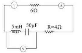
In the shown AC source, the voltage is given as V = 20 cos 2000t. Neglecting source resistance, the voltmeter and ammeter readings will be:
The same current is flowing in two AC circuits. The first circuit contains a pure inductor and the second, a capacitor. If the frequency of the AC is increased, then the current will:
A 25 μF capacitor, a 0.10 H inductor, and a 25 Ω resistor is connected in series with an AC source of emf ε = 310 sin 314t. What is the frequency of the AC source?
The same current is flowing in two AC circuits. The first circuit contains a pure inductor and the second, a capacitor. If the frequency of the AC is increased, then the current will:
A 25 μF capacitor, a 0.10 H inductor, and a 25 Ω resistor is connected in series with an AC source of emf ε = 310 sin 314t. What is the frequency of the AC source?


