All induction type transducers are based on
Faraday's law
Induction Transducers and Their Fundamental Principle
Induction type transducers are a class of sensors that convert physical quantities like displacement, velocity, or vibration into an electrical signal. Their operation relies on the principle of electromagnetic induction, which is precisely described by Faraday's law. This law forms the core foundation for how these transducers generate an output signal in response to a change in the measured quantity.
Faraday's Law of Electromagnetic Induction Explained
Faraday's law of electromagnetic induction states that a change in magnetic flux passing through a coil induces an electromotive force (EMF) or voltage across the coil. This induced EMF is directly proportional to the rate of change of the magnetic flux. In simpler terms, if the amount of magnetic field lines (flux) passing through a coil changes, an electrical voltage will be produced in that coil.
Mathematically, Faraday's law can be expressed as:
$$ \text{EMF} = -N \frac{d\Phi}{dt} $$
Where:
- $\text{EMF}$ is the induced electromotive force (voltage).
- $N$ is the number of turns in the coil.
- $\Phi$ is the magnetic flux linked with the coil.
- $\frac{d\Phi}{dt}$ is the rate of change of magnetic flux with respect to time.
- The negative sign indicates Lenz's law, meaning the induced EMF opposes the change in magnetic flux.
Induction Transducers: Applying Faraday's Law
In induction type transducers, the physical quantity being measured (e.g., displacement) is converted into a change in magnetic flux. This change in magnetic flux then induces a voltage in a coil, as per Faraday's law.
- For example, in a Linear Variable Differential Transformer (LVDT), a common induction type transducer, the linear displacement of a core within coils changes the magnetic coupling between primary and secondary windings. This change in coupling alters the magnetic flux through the secondary coils, inducing a voltage proportional to the displacement.
- Similarly, in rotary variable differential transformers (RVDTs) or variable reluctance transducers, the movement of a magnetic material or a change in the coil's geometry leads to a variation in magnetic flux, thereby inducing an output voltage based on Faraday's law.
Analysis of Other Principles
Let's briefly look at why the other options are not the fundamental basis for induction type transducers:
- Ohm's law: This law describes the relationship between voltage, current, and resistance in an electrical circuit ($V=IR$). While it applies to the circuits used with transducers, it does not explain the fundamental principle of how the transducer itself converts a physical quantity into an electrical signal through induction.
- Seebeck effect: This effect describes the phenomenon where a temperature difference between two dissimilar electrical conductors or semiconductors produces a voltage difference between them. This is the operating principle behind thermocouples, which are temperature transducers, not induction type transducers.
- Peltier effect: This effect is the inverse of the Seebeck effect, where a temperature difference is created when an electric current flows through a junction of two dissimilar conductors. It is used in thermoelectric cooling devices, not as the basis for induction type transducers.
Therefore, the core principle governing all induction type transducers is indeed Faraday's law, which dictates how changes in magnetic fields generate electrical signals.
Important Questions from Faraday's Law
In the table shown, List I and List II, respectively, contain terms appearing on the left-hand side and the right-hand side of Maxwell’s equations (in their standard form). Match the left-hand side with the corresponding right-hand side.
List I
List II
1.
∇. D
P
0
2.
∇ × E
Q
\(\rho_v\)
3.
∇. B
R
\( - \frac{{\partial B}}{{\partial t}}\)
4.
∇ × H
S
\(J+ \frac{{\partial D}}{{\partial t}}\)
“By the motion of the conductor or the coil in a magnetic field, i.e., the magnetic field is stationary and the moving conductors cut through it. The EMF generated in this way is normally called dynamically induced EMF.”
The given statement is specified by which of the following laws?
A flux of 0.25 mWb is produced by a coil of 1000 turns wound on a ring with a current of 2 A in it. Calculate the e.m.f induced in the coil when a current of 10 A is switched off, assuming the current will fall to zero in 1 millisecond.
Which of the following law states that “whenever the magnetic flux linked with a conductor or coil changes, an emf is induced in it?
The figure shows an arbitrarily shaped planar conducting loop A in the XY plane. Two nonintersecting regions with areas $a_1$ and $a_2$ within the loop are subjected to magnetic fields $\vec{B}_1 = \frac{m}{\sqrt{2}} \sin(\omega t) (1\hat{x} + 0\hat{y} + 1\hat{z})$, and
$\vec{B}_2 = -\frac{n}{\sqrt{2}} \cos(2\omega t + \pi/4) (0\hat{x} + 1\hat{y} + 1\hat{z})$, respectively.
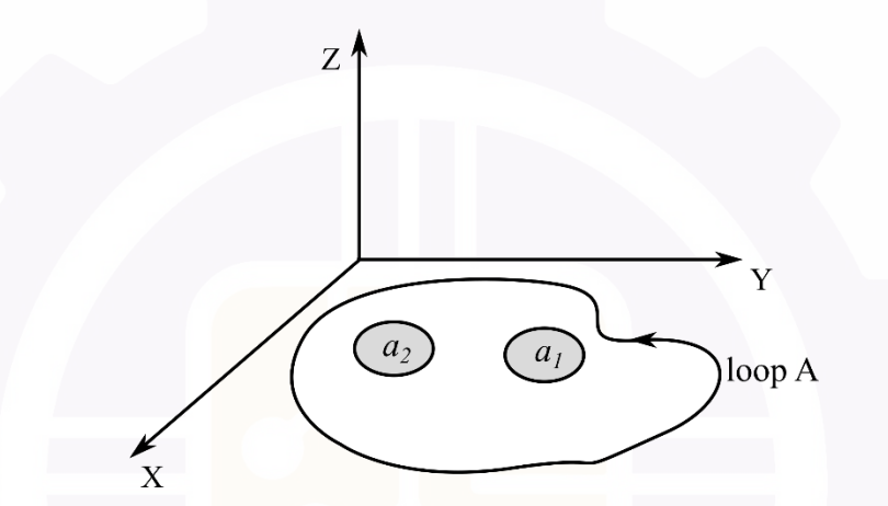
What is the expression for the induced rms voltage in loop A?