
A transistor has ______ PN junctions
2
Transistor Structure: Understanding PN Junctions
A transistor is a semiconductor device primarily used to amplify or switch electronic signals and electrical power. It is fundamental to modern electronic devices.
The Role of PN Junctions in Transistors
The operation of many common types of transistors relies on the properties of semiconductor junctions, specifically PN junctions. A PN junction is formed when a P-type semiconductor (with an excess of holes) is brought into contact with an N-type semiconductor (with an excess of electrons).
Types of Transistors and Their Junctions
The most common type of transistor discussed in introductory electronics is the Bipolar Junction Transistor (BJT). BJTs come in two configurations:
- NPN Transistor: This type consists of a thin layer of P-type material sandwiched between two layers of N-type material (N-P-N).
- PNP Transistor: This type consists of a thin layer of N-type material sandwiched between two layers of P-type material (P-N-P).
In both NPN and PNP configurations, there are two distinct PN junctions formed:
- In an NPN transistor, the junctions are between the N region (Emitter) and the P region (Base), and between the P region (Base) and the N region (Collector).
- In a PNP transistor, the junctions are between the P region (Emitter) and the N region (Base), and between the N region (Base) and the P region (Collector).
Therefore, a standard bipolar transistor fundamentally contains two PN junctions.
Conclusion
Based on the structure of bipolar junction transistors (BJTs), which are the most common type referred to when discussing transistor junctions, the correct answer is that a transistor has two PN junctions.
Important Questions from Transistors
Which of the following is not true for a BJT?
A transistor amplifier with proper biasing has the following measured parameters:
Input resistance = 1 kΩ, Output resistance = 10 kΩ, Current gain = 90.
Identity the biasing configuration.
The change of output wave shape from the input wave shape of an amplifier is known as
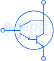
Identify the component shown in the image below:
The emitter current of a transistor is 1 mA. If 1% of the emitted current carriers are lost in the base recombination, what is the value β? Identify from the given options.


