
A transistor amplifier with proper biasing has the following measured parameters: Input resistance = 1 kΩ, Output resistance = 10 kΩ, Current gain = 90. Identity the biasing configuration.
Common emitter
Analyzing Transistor Amplifier Biasing Configurations
The question asks us to identify the biasing configuration of a transistor amplifier based on its measured parameters: input resistance ($R_{in}$), output resistance ($R_{out}$), and current gain ($A_i$). The given values are $R_{in} = 1 \, k\Omega$, $R_{out} = 10 \, k\Omega$, and $A_i = 90$. We need to compare these values with the typical characteristics of the common configurations: Common Base (CB), Common Emitter (CE), and Common Collector (CC).
Common Base (CB) Configuration Characteristics
- Input Resistance ($R_{in}$): Typically very low (on the order of tens of ohms, e.g., $R_{in} \approx 50 \, \Omega$).
- Output Resistance ($R_{out}$): Typically very high (on the order of hundreds of kΩ to MΩ, e.g., $R_{out} \approx 50 \, k\Omega$ or higher).
- Current Gain ($A_i$): Approximately unity ($A_i \approx 1$).
- Voltage Gain ($A_v$): High.
The measured parameters ($R_{in} = 1 \, k\Omega$, $R_{out} = 10 \, k\Omega$, $A_i = 90$) do not match the characteristics of the Common Base configuration, especially the low input resistance and unity current gain.
Common Emitter (CE) Configuration Characteristics
- Input Resistance ($R_{in}$): Typically medium (on the order of kΩ, e.g., $R_{in} \approx 1 \, k\Omega$ to $5 \, k\Omega$).
- Output Resistance ($R_{out}$): Typically medium to high (on the order of tens of kΩ, e.g., $R_{out} \approx 40 \, k\Omega$ to $50 \, k\Omega$).
- Current Gain ($A_i$): High (significantly greater than 1, typically ranging from 50 to 200).
- Voltage Gain ($A_v$): High.
The measured parameters ($R_{in} = 1 \, k\Omega$, $R_{out} = 10 \, k\Omega$, $A_i = 90$) closely align with the typical characteristics of the Common Emitter configuration. The input resistance is in the kΩ range, the current gain is high (90), and the output resistance is in the tens of kΩ range.
Common Collector (CC) Configuration Characteristics
- Input Resistance ($R_{in}$): Typically high (on the order of hundreds of kΩ to MΩ).
- Output Resistance ($R_{out}$): Typically very low (on the order of tens of ohms, e.g., $R_{out} \approx 100 \, \Omega$).
- Current Gain ($A_i$): High (often > 100).
- Voltage Gain ($A_v$): Slightly less than unity ($A_v < 1$).
The measured parameters do not match the Common Collector configuration. Specifically, the output resistance is too high ($10 \, k\Omega$ vs. low ohms), and while the current gain is high, the input resistance is lower than typically expected for a CC configuration.
Darlington Pair Characteristics
A Darlington pair is a compound configuration offering very high current gain and high input impedance, usually much higher than $1 \, k\Omega$. While it provides high gain, the parameter values provided ($R_{in} = 1 \, k\Omega$, $R_{out} = 10 \, k\Omega$) are more representative of a single CE stage rather than a Darlington pair, which typically has $R_{in}$ in the range of $10 \, k\Omega$ to $M\Omega$ and lower $R_{out}$.
Comparison of Configurations
| Configuration | Typical $R_{in}$ | Typical $R_{out}$ | Typical $A_i$ | Given Parameters |
|---|---|---|---|---|
| Common Base (CB) | Low (tens $\Omega$) | High (100s k$\Omega$) | $\approx 1$ | $R_{in}=1 \, k\Omega$, $R_{out}=10 \, k\Omega$, $A_i=90$ |
| Common Emitter (CE) | Medium (k$\Omega$) | Medium (10s k$\Omega$) | High (> 50) | Matches Closely |
| Common Collector (CC) | High (100s k$\Omega$ - M$\Omega$) | Low (tens $\Omega$) | High (> 100) | $R_{in}=1 \, k\Omega$, $R_{out}=10 \, k\Omega$, $A_i=90$ |
Conclusion on Biasing Configuration
Based on the comparison, the measured parameters ($R_{in} \approx 1 \, k\Omega$, $R_{out} \approx 10 \, k\Omega$, $A_i \approx 90$) are most consistent with the characteristics of a Common Emitter amplifier configuration.
Important Questions from Transistors
A transistor has ______ PN junctions
Which of the following is not true for a BJT?
The change of output wave shape from the input wave shape of an amplifier is known as
Identify the component shown in the image below:
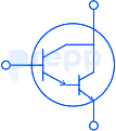
The emitter current of a transistor is 1 mA. If 1% of the emitted current carriers are lost in the base recombination, what is the value β? Identify from the given options.


