A capacitor $C_1 = 1.0 \mu F$ is charged up to a voltage $V = 60$ V by connecting it to battery B through switch (1). Now $C_1$ is disconnected from battery and connected to a circuit consisting of two uncharged capacitors $C_2 = 3.0 \mu F$ and $C_3 = 6.0 \mu F$ through switch (2), as shown in the figure. The sum of final charges on $C_2$ and $C_3$ is :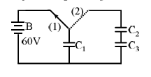
To solve this problem, we need to calculate the total charge on the capacitors \(C_2\) and \(C_3\) after they are connected to the charged capacitor \(C_1\). Here are the steps to solve the problem:
Step 1: Calculate the initial charge on \(C_1\).
The charge \(Q_1\) on the capacitor \(C_1\) can be determined using the formula:
\(Q = CV\)
Where:
- \(C = 1.0 \, \mu \text{F}\)
- \(V = 60 \, \text{V}\)
Thus,
\(Q_1 = 1.0 \times 60 = 60 \, \mu \text{C}\)
Step 2: Determine the equivalent capacitance when \(C_1\) is connected to \(C_2\) and \(C_3\).
The capacitors \(C_2\) and \(C_3\) are connected in series, so the equivalent capacitance \(C_{\text{eq}}\) is given by:
\(\frac{1}{C_{\text{eq}}} = \frac{1}{C_2} + \frac{1}{C_3}\)
Substituting the given values:
\(\frac{1}{C_{\text{eq}}} = \frac{1}{3} + \frac{1}{6} = \frac{2}{6} + \frac{1}{6} = \frac{3}{6} = \frac{1}{2}\)
Thus, \(C_{\text{eq}} = 2 \, \mu \text{F}\)
Step 3: Calculate the final charge distribution.
When \(C_1\) is connected to the equivalent capacitance \(C_{\text{eq}}\), the total charge is conserved. The initial charge on \(C_1\) is now distributed over \(C_1\) and the series combination \(C_2\) and \(C_3\).
The new combined capacitance becomes:
\(C_{\text{total}} = C_1 + C_{\text{eq}} = 1 + 2 = 3 \, \mu \text{F}\)
The voltage across the capacitors is:
\(V_{\text{final}} = \frac{Q_1}{C_{\text{total}}} = \frac{60}{3} = 20 \, \text{V}\)
Hence, the charge on the series combination \((Q_2 = Q_3)\) is:
\(Q_2 = C_{\text{eq}} \times V_{\text{final}} = 2 \times 20 = 40 \, \mu \text{C}\)
Conclusion: The sum of the final charges on \(C_2\) and \(C_3\) is \(40 \, \mu \text{C}\).
Similar Questions
- The electric field of a plane electromagnetic wave, travelling in an unknown non-magnetic medium is given by,
$E_y = 20 \sin(3 \times 10^6 x - 4.5 \times 10^{14} t) \text{ V/m}$
(where x, t and other values have S.I. units). The dielectric constant of the medium is _________.
(speed of light in free space is $3 \times 10^8 \text{ m/s}$) - A cylindrical conductor of length 2 m and area of cross-section $0.2 \text{ mm}^2$ carries an electric current of 1.6 A when its ends are connected to a 2 V battery. Mobility of electrons in the conductor is $\alpha \times 10^{-3} \text{ m}^2\text{/V.s}$. The value of $\alpha$ is :
(electron concentration $= 5 \times 10^{28} \text{/m}^3$ and electron charge = $1.6 \times 10^{-19} \text{ C}$) - A short bar magnet placed with its axis at $30^\circ$ with an external field of 800 Gauss, experiences a torque of 0.016 N.m. The work done in moving it from most stable to most unstable position is $\alpha \times 10^{-3} \text{ J}$. The value of $\alpha$ is ______.
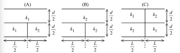
Three parallel plate capacitors each with area $A$ and separation $d$ are filled with two dielectric ($k_1$ and $k_2$) in the following fashion. Which of the following is true? ($k_1 > k_2$)
- A moving coil galvanometer of resistance $100 \text{ }\Omega$ shows a full scale deflection for a current of $1 \text{ mA}$. The value of resistance required to convert this galvanometer into an ammeter, showing full scale deflection for a current of $5 \text{ mA}$, is _______ $\Omega$
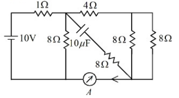
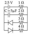
The reading of the ammeter ($A$) in steady state in the following circuit (assuming negligible internal resistance of the ammeter) is _______ A.
- A capacitor $C$ is first charged fully with potential difference of $V_0$ and disconnected from the battery. The charged capacitor is connected across an inductor having inductance $L$. In $t\text{ s}$ $25\%$ of the initial energy in the capacitor is transferred to the inductor. The value of $t$ is __________ $\text{s}$.
The charge stored by the capacitor $C$ in the given circuit in the steady state is __________ $\mu\text{C}$.
- An electromagnetic wave of frequency $100\text{ MHz}$ propagates through a medium of conductivity, $\sigma = 10\text{ mho/m}$. The ratio of maximum conduction current density to maximum displacement current density is __________.
$\left[ \text{Take } \frac{1}{4\pi\varepsilon_0} = 9 \times 10^9\text{ Nm}^2\text{/C}^2 \right]$ - An inductor stores $16\text{ J}$ of magnetic field energy and dissipates $32\text{ W}$ of thermal energy due to its resistance when an a.c. current of $2\text{ A}$ (rms) and frequency $50\text{ Hz}$ flows through it. The ratio of inductive reactance to its resistance is _________. ($\pi = 3.14$)
Important Questions from Electricity and Magnetism
- The electric field of a plane electromagnetic wave, travelling in an unknown non-magnetic medium is given by,
$E_y = 20 \sin(3 \times 10^6 x - 4.5 \times 10^{14} t) \text{ V/m}$
(where x, t and other values have S.I. units). The dielectric constant of the medium is _________.
(speed of light in free space is $3 \times 10^8 \text{ m/s}$) - A cylindrical conductor of length 2 m and area of cross-section $0.2 \text{ mm}^2$ carries an electric current of 1.6 A when its ends are connected to a 2 V battery. Mobility of electrons in the conductor is $\alpha \times 10^{-3} \text{ m}^2\text{/V.s}$. The value of $\alpha$ is :
(electron concentration $= 5 \times 10^{28} \text{/m}^3$ and electron charge = $1.6 \times 10^{-19} \text{ C}$) - A short bar magnet placed with its axis at $30^\circ$ with an external field of 800 Gauss, experiences a torque of 0.016 N.m. The work done in moving it from most stable to most unstable position is $\alpha \times 10^{-3} \text{ J}$. The value of $\alpha$ is ______.
Three parallel plate capacitors each with area $A$ and separation $d$ are filled with two dielectric ($k_1$ and $k_2$) in the following fashion. Which of the following is true? ($k_1 > k_2$)
- A moving coil galvanometer of resistance $100 \text{ }\Omega$ shows a full scale deflection for a current of $1 \text{ mA}$. The value of resistance required to convert this galvanometer into an ammeter, showing full scale deflection for a current of $5 \text{ mA}$, is _______ $\Omega$