
Analyzing Magnetic Fields and Flux Change
Coil $C_1$ carries current $I$ in an anti-clockwise direction. Using the right-hand rule, this generates a magnetic field along the common axis directed, let's say, towards the right (positive direction). Coil $C_3$ carries current $I$ in a clockwise direction. This generates a magnetic field along the axis directed towards the left (negative direction).
At the location of coil $C_2$, which is midway, the net magnetic field $B_{net}$ is the difference between the field contributions from $C_1$ ($B_1$) and $C_3$ ($B_3$). We can represent this as $B_{net} = B_1 - B_3$, where $B_1$ and $B_3$ are the magnitudes of the magnetic fields generated by $C_1$ and $C_3$ respectively at $C_2$. The net magnetic flux through $C_2$ is proportional to $B_{net}$.
Evaluating Motion Conditions (Option C)
Let's analyze the effect of the motion described in Option C: $C_1$ moves towards $C_2$ and $C_3$ moves away from $C_2$.
- When $C_1$ moves towards $C_2$, the distance between them ($d_{12}$) decreases. This causes the magnetic field $B_1$ from $C_1$ at $C_2$ to increase. Thus, $\Delta B_1 > 0$.
- When $C_3$ moves away from $C_2$, the distance between them ($d_{23}$) increases. This causes the magnetic field $B_3$ from $C_3$ at $C_2$ to decrease. Thus, $\Delta B_3 < 0$.
The change in the net magnetic field is $\Delta B_{net} = \Delta B_1 - \Delta B_3$. Substituting the signs of the changes:
$\Delta B_{net} = (+ \text{ve}) - (- \text{ve}) = (+ \text{ve}) + (+ \text{ve})$
This means $\Delta B_{net}$ is definitely positive. Therefore, the net magnetic flux through $C_2$ is increasing in the positive direction (the direction of the field from $C_1$).
Applying Lenz's Law for Induced Current Direction
According to Lenz's Law, an induced current flows in a direction that opposes the change in magnetic flux that produced it.
Since the net magnetic flux through $C_2$ is increasing in the positive direction, the induced current in $C_2$ must create a magnetic field that opposes this increase. This opposing field must be in the negative direction (opposite to the field from $C_1$).
A clockwise current in coil $C_2$ generates a magnetic field pointing in the negative direction (towards the left, opposing the increasing flux from $C_1$). Therefore, the induced current in $C_2$ will be in the clockwise direction under these conditions.
Similar Questions
- The electric current in the circuit is given as $i = i_o(t/T)$. The r.m.s current for the period $t = 0$ to $t = T$ is ________.
- In the potentiometer, when the cell in the secondary circuit is shunted with $4\text{ }\Omega$ resistance, the balance is obtained at the length $120\text{ cm}$ of wire. Now when the same cell is shunted with $12\text{ }\Omega$ resistance, the balance is shifted to a length of $180\text{ cm}$. The internal resistance of cell is ________$\Omega$
- The electric field of an electromagnetic wave travelling through a medium is given by $\vec{E}(x,t) = 25 \sin(2.0 \times 10^{15} t - 10^7 x) \hat{n}$
then the refractive index of the medium is ________.
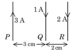
(All given measurement are in SI units) Three long straight wires carrying current are arranged mutually parallel as shown in the figure. The force experienced by $15 \text{ cm}$ length of wire $Q$ is________.
$(\mu_o = 4\pi \times 10^{-7} \text{ T.m/A})$- For the two cells having same EMF $E$ and internal resistance $r$, the current passing through the external resistor $6\text{ }\Omega$ is same when both the cells are connected either in parallel or in series. The value of internal resistance $r$ is ________$\Omega$.
- The magnetic field at the centre of a current carrying circular loop of radius $R$ is $16 \text{ \mu T}$. The magnetic field at a distance $x = \sqrt{3}R$ on its axis from the centre is ________$\text{\mu T}$.
- Two point charges of $1 \text{ nC}$ and $2 \text{ nC}$ are placed at the two corners of equilateral triangle of side $3 \text{ cm}$. The work done in bringing a charge of $3 \text{ nC}$ from infinity to the third corner of the triangle is ________$\text{\mu J}$.
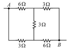
$\frac{1}{4\pi\epsilon_0} = 9 \times 10^9 \text{ N.m}^2\text{/C}^2$ The equivalent resistance between the points $A$ and $B$ in the following circuit is $\frac{x}{5} \text{ }\Omega$. The value of $x$ is ________.
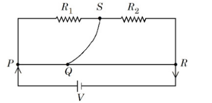
A meter bridge with two resistances $R_1$ and $R_2$ as shown in figure was balanced (null point) at 40 cm from the point $P$. The null point changed to 50 cm from the point $P$, when $16 \ \Omega$ resistance is connected in parallel to $R_2$. The values of resistances $R_1$ and $R_2$ are _________.
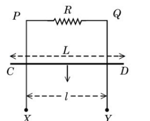
XPQY is a vertical smooth long loop having a total resistance $R$ where PX is parallel to QY and separation between them is $l$. A constant magnetic field $B$ perpendicular to the plane of the loop exists in the entire space. A rod CD of length $L \ (L > l)$ and mass $m$ is made to slide down from rest under the gravity as shown in figure. The terminal speed acquired by the rod is _________ m/s. (g = acceleration due to gravity)
Important Questions from Electricity and Magnetism
- The electric current in the circuit is given as $i = i_o(t/T)$. The r.m.s current for the period $t = 0$ to $t = T$ is ________.
- In the potentiometer, when the cell in the secondary circuit is shunted with $4\text{ }\Omega$ resistance, the balance is obtained at the length $120\text{ cm}$ of wire. Now when the same cell is shunted with $12\text{ }\Omega$ resistance, the balance is shifted to a length of $180\text{ cm}$. The internal resistance of cell is ________$\Omega$
- The electric field of an electromagnetic wave travelling through a medium is given by $\vec{E}(x,t) = 25 \sin(2.0 \times 10^{15} t - 10^7 x) \hat{n}$
then the refractive index of the medium is ________.
(All given measurement are in SI units) Three long straight wires carrying current are arranged mutually parallel as shown in the figure. The force experienced by $15 \text{ cm}$ length of wire $Q$ is________.
$(\mu_o = 4\pi \times 10^{-7} \text{ T.m/A})$- For the two cells having same EMF $E$ and internal resistance $r$, the current passing through the external resistor $6\text{ }\Omega$ is same when both the cells are connected either in parallel or in series. The value of internal resistance $r$ is ________$\Omega$.


