
The RLC filter shown below acts as a ________. 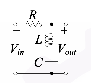
The given RLC circuit acts as a band stop filter. Let's understand why this is the case with a step-by-step explanation.
Understanding RLC Circuits: An RLC circuit consists of a resistor (R), an inductor (L), and a capacitor (C) connected in series or parallel. These components are used to filter signals by allowing certain frequencies to pass while blocking others.
Types of Filters:
- Low pass filter allows low frequencies and attenuates high frequencies.
- High pass filter allows high frequencies and attenuates low frequencies.
- Band pass filter allows a specific band of frequencies to pass and attenuates frequencies outside this band.
- Band stop filter, also known as a notch filter, attenuates a specific band of frequencies and allows frequencies outside this band to pass.
Working of Band Stop Filter:
The given RLC circuit is a parallel resonant circuit. In a parallel resonance, at the resonant frequency, the impedance becomes very high, creating a notch at this frequency. Therefore, frequencies around this notch are blocked or significantly attenuated, effectively acting as a band stop filter.
Conclusion:
The RLC filter shown in the image is configured to block a particular band of frequencies. This configuration is characteristic of a band stop filter.
Thus, the correct answer is: band stop filter.
Important Questions from Filters
In choke input filter circuit, the first element is _______.
In the frequency response graph of an amplifier the 3 dB point refers to :
Which of the following statements is NOT correct for a Chebyshev Filter?
Which of the following statements is NOT correct about Butterworth filter?
The characteristic equation for the output voltage of an All‐pass filter is given by:


