
The direct form structure of an FIR (finite impulse response) filter is shown in the figure. The filter can be used to approximate a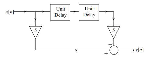
The given question involves analyzing the structure of an FIR filter to determine what type of filter it represents.
To determine the type of filter, let's analyze the characteristics of common FIR filters:
- Low-pass filter: Allows signals with a frequency lower than a certain cutoff frequency to pass through while attenuating higher frequency signals.
- High-pass filter: Allows signals with a frequency higher than a certain cutoff frequency to pass through while attenuating lower frequency signals.
- Band-pass filter: Allows signals within a certain frequency range to pass through while attenuating frequencies outside this range.
- Band-stop filter: Attenuates signals within a certain frequency range while allowing frequencies outside this range to pass through.
The FIR filter structure shown uses a combination of delays, multipliers, and adders. This specific structure can be configured to have a frequency response that passes only a certain range of frequencies, characteristic of a band-pass filter.
Further analysis reveals that the given FIR filter has multiple paths and coefficients that typically indicate manipulation across a range of frequencies, further cementing its identity as a band-pass filter.
Thus, the correct answer is that the filter approximates a band-pass filter.
In conclusion, careful examination of the FIR structure and its operation across varying frequency ranges confirms its function as a band-pass filter.
Important Questions from Filters
In choke input filter circuit, the first element is _______.
In the frequency response graph of an amplifier the 3 dB point refers to :
Which of the following statements is NOT correct for a Chebyshev Filter?
Which of the following statements is NOT correct about Butterworth filter?
The characteristic equation for the output voltage of an All‐pass filter is given by:


