
The dynamic characteristics of capacitive transducers are similar to those of
High Pass Filter
Understanding Capacitive Transducer Dynamic Characteristics
A capacitive transducer works by converting a physical quantity (like pressure, displacement, or level) into a change in capacitance. The dynamic characteristics describe how effectively and quickly the transducer responds to changes in the input quantity over time. These characteristics are crucial for understanding the transducer's performance in measuring varying signals.
Capacitive Transducers and Frequency Response
The behavior of a capacitor in an electrical circuit is frequency-dependent. Its impedance, denoted as $Z_C$, is given by the formula:
$Z_C = \frac{1}{j\omega C}$
where $j$ is the imaginary unit, $\omega$ is the angular frequency ($\omega = 2\pi f$, with $f$ being the frequency), and $C$ is the capacitance.
- At very low frequencies (approaching DC or $f=0$), the impedance $Z_C$ becomes very high (approaching infinity), meaning the capacitor effectively blocks DC signals or very slow changes.
- At very high frequencies ($f \to \infty$), the impedance $Z_C$ approaches zero, meaning the capacitor acts like a short circuit and allows high-frequency signals to pass easily.
This frequency-dependent behavior means that capacitive transducers, when incorporated into measurement circuits, often respond more strongly to rapid changes (higher frequencies) in the measured quantity than to slow changes or constant values (lower frequencies or DC). They tend to attenuate or block signals below a certain frequency threshold.
Comparing Transducer Behavior to Filters
Electronic filters are designed to allow signals within certain frequency ranges to pass while blocking others. Let's look at the options:
- Low Pass Filter: Allows low frequencies to pass and attenuates high frequencies.
- High Pass Filter: Allows high frequencies to pass and attenuates low frequencies (including DC).
- Notch Filter (Band-stop Filter): Attenuates signals within a specific, narrow frequency band while allowing others to pass.
Similarity to High Pass Filter
The dynamic response of many capacitive transducers closely mimics that of a High Pass Filter. This is because:
- Capacitors inherently block DC signals.
- Their impedance decreases as frequency increases, allowing faster-changing signals (higher frequencies) to pass through more easily compared to slower-changing signals (lower frequencies).
This characteristic is useful because it helps in filtering out unwanted DC offsets or slow drifts in the measured signal, allowing the transducer system to focus on the dynamic variations of interest. The transducer effectively responds to the rate of change, similar to how a high-pass filter shapes the signal's frequency content.
Important Questions from Capacitive Transducers
- What device would you use to measure the output of a thermocouple ?
An air filled parallel plate electrostatic actuator is shown in the figure. The area of each capacitor plate is $100 \mu m \times 100 \mu m$. The distance between the plates $d_0 = 1 \mu m$ when both the capacitor charge and spring restoring force are zero as shown in Figure (a). A linear spring of constant $k=0.01 N/m$ is connected to the movable plate. When charge is supplied to the capacitor using a current source, the top plate moves as shown in Figure (b). The magnitude of minimum charge (Q) required to momentarily close the gap between the plates is _________ $\times 10^{-14} C$ (rounded off to two decimal places).
Note: Assume a full range of motion is possible for the top plate and there is no fringe capacitance. The permittivity of free space is $\epsilon_0 =8.85\times 10^{-12} F/m$ and relative permittivity of air ($\epsilon_r$) is 1.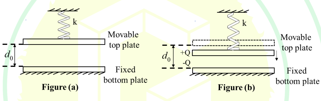
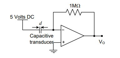
A capacitive motion transducer circuit is shown. The gap $d$ between the parallel plates of the capacitor is varied as $d(t)=10^{-3}[1+0.1\sin(1000\pi t)]$ m. If the value of the capacitance is 2pF at $t = 0$ ms, the output voltage $V_o$ at $t = 2$ ms is
- A differential push-pull type capacitive displacement sensor (nominal capacitance $C_0 = 0.01 \text{ }\mu F$) is connected in two adjacent arms of an ac bridge in such a way that the output voltage of the bridge is independent of the frequency of the supply voltage. Supply to the bridge is $1\text{V}$ at $1 \text{ kHz}$, and two equal resistances ($R = 3.9 \text{ k}\Omega$) are placed in the other two arms of the bridge. The bridge sensitivity is
A parallel plate capacitive displacement sensor has a plate area of $2\text{ cm}^2$. The air gap between the plates is decreased by $0.1\text{ mm}$ from an initial value of $0.5\text{ mm}$. The percentage change in the capacitance value is ______ %.
(Assume permittivity as $\epsilon_0 = 8.854 \times 10^{-12}\text{ F/m}$)


