
The circuit shown is a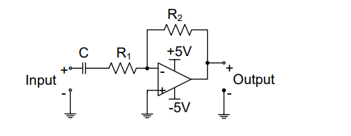
To determine the type of filter shown in the circuit and calculate the cut-off frequency, let's analyze the given circuit step-by-step.
The circuit presented is a configuration involving a capacitor \( C \) and resistor \( R_1 \) at the input side, connected to an operational amplifier. This setup suggests a typical high pass filter configuration.
- In a high pass filter, the capacitor \( C \) blocks any low-frequency signal until the frequency is sufficiently high for the capacitor to allow it through, thereby 'passing' high frequencies while attenuating low frequencies.
- The input capacitor \( C \) and the resistor \( R_1 \) together form the initial filtering stage.
- The operational amplifier (op-amp) is configured to boost the signal, ensuring that only frequencies above the calculated cutoff frequency (\( f_{3dB} \)) are significantly affected.
Cut-off Frequency Calculation:
The cut-off frequency for a high pass filter can be calculated using the formula:
\(f_{3dB} = \frac{1}{2 \pi R_1 C}\)
Since the answer mentions the angular frequency in rad/s, the expression becomes:
\(f_{3dB} = \frac{1}{R_1 C} \text{ rad/s}\)
This matches the correct answer choice:
- High pass filter with \(f_{3dB} = \frac{1}{R_1 C}\) rad/s
Therefore, the given circuit is a high pass filter with the specified cut-off frequency.
Important Questions from Filters
In choke input filter circuit, the first element is _______.
In the frequency response graph of an amplifier the 3 dB point refers to :
Which of the following statements is NOT correct for a Chebyshev Filter?
Which of the following statements is NOT correct about Butterworth filter?
The characteristic equation for the output voltage of an All‐pass filter is given by:


