
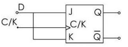
Converting J-K Flip-Flop to D Flip-Flop
A D Flip-Flop is a fundamental unit in sequential digital logic circuits. It stores a single bit of data. Its primary characteristic is that the output $Q$ takes the value of the input $D$ upon the active clock edge.
A J-K Flip-Flop is a more versatile flip-flop with two inputs, $J$ and $K$. Its behavior depends on the combination of $J$ and $K$ inputs:
- If $J=0$ and $K=0$, the flip-flop state remains unchanged.
- If $J=0$ and $K=1$, the flip-flop resets (output $Q$ becomes 0).
- If $J=1$ and $K=0$, the flip-flop sets (output $Q$ becomes 1).
- If $J=1$ and $K=1$, the flip-flop toggles its state (output $Q$ flips from 0 to 1 or 1 to 0).
To obtain a D Flip-Flop behavior from a J-K Flip-Flop, we need to ensure that the output $Q$ always follows the input $D$ after the clock pulse. We can achieve this by appropriately connecting the $J$ and $K$ inputs to the $D$ input.
Circuit Modification for D Flip-Flop
The standard method to convert a J-K Flip-Flop into a D Flip-Flop involves the following connections:
- Connect the D input of the desired D Flip-Flop to the J input of the J-K Flip-Flop.
- Connect the D input of the desired D Flip-Flop to the input of a NOT gate.
- Connect the output of the NOT gate to the K input of the J-K Flip-Flop.
Essentially, this means setting $J = D$ and $K = \bar{D}$.
Analyzing the Conversion Logic
Let's see how these connections make the J-K Flip-Flop behave like a D Flip-Flop:
- Case 1: Input $D = 0$
- According to our connections, $J = D = 0$.
- $K = \bar{D} = \bar{0} = 1$.
- With $J=0$ and $K=1$, the J-K Flip-Flop resets, meaning the output $Q$ becomes 0. Thus, $Q_{next} = 0$, which matches $D$.
- Case 2: Input $D = 1$
- According to our connections, $J = D = 1$.
- $K = \bar{D} = \bar{1} = 0$.
- With $J=1$ and $K=0$, the J-K Flip-Flop sets, meaning the output $Q$ becomes 1. Thus, $Q_{next} = 1$, which matches $D$.
In both possible input states for $D$, the resulting state transition of the J-K Flip-Flop makes the output $Q$ equal to the input $D$ after the clock edge. This confirms that connecting $J = D$ and $K = \bar{D}$ effectively transforms a J-K Flip-Flop into a D Flip-Flop.
The circuit modification described ensures that the forbidden state ($J=1, K=1$) of the J-K Flip-Flop is never reached, as $J$ and $K$ are always complements of each other.
Important Questions from Flip Flops and Counters
Race around condition can be removed by using the combination of:
A JK flip flop with J = K = 1 has a 100 kHz clock input. The Q output is
A ring counter with 5 flip-flops will have:
A 4 bit counter is used to count form 0, 1, 2 …. n. Value of ‘n’ is
Counter design can be implemented by:


