
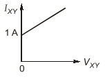
The I-V characteristics of the elements between the nodes X and Y is best depicted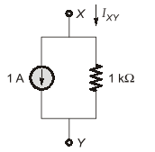
To solve this problem, we need to analyze the circuit given between nodes X and Y. The circuit shows a 1 A current source and a 1 kΩ resistor in parallel.
To determine the I-V characteristics (current-voltage characteristics) of this circuit, consider the following:
-
The 1 A current source ensures a constant current of 1 A is maintained through the circuit, irrespective of the voltage across it. This means the current I_{XY} is constant at 1 A.
-
The voltage across the resistor is given by Ohm's law: V = IR. For a 1 kΩ resistor with a 1 A current, the voltage V_{XY} is:
V = 1 \text{ A} \times 1000 \, \Omega = 1000 \, \text{V}.
-
Since the current is constant, the voltage across the circuit is also constant. This implies the I-V characteristics will be a straight line parallel to the voltage axis at I = 1 \text{ A}.
Thus, the I-V characteristic graph for the given elements is a horizontal line at I = 1 \text{ A}, corresponding to a vertical line because the voltage is constant.
The correct I-V characteristics graph is depicted as:
This option shows a vertical line at V = 1000 \, \text{V} which corresponds to a constant current as we derived.
Important Questions from Circuit Elements
A color code of orange, orange, orange is for what ohmic value?
In wire-wound standard resistor, the bifilar winding is adopted to reduce ______.
Change in resistance of a conductor on increasing its length 3 times will be
The voltage induced in an inductor is represented as
Which component opposes voltage change?


