In a half-subtractor circuit with X and Y as inputs, the Borrow (M) and Difference (N = X - Y) are given by
M = X̅Y, N = X ⊕ Y
Half-Subtractor Circuit Overview
A half-subtractor is a combinational logic circuit that performs subtraction of two single-bit binary numbers. It takes two inputs, usually denoted as X (minuend) and Y (subtrahend), and produces two outputs: Difference (N) and Borrow (M).
The operation of a half-subtractor can be understood by looking at its truth table, which shows the outputs for all possible combinations of inputs.
Truth Table for Half-Subtractor
Let's construct the truth table for a half-subtractor with inputs X and Y, and outputs Difference (N) and Borrow (M).
| X (Minuend) | Y (Subtrahend) | N (Difference = X - Y) | M (Borrow) |
|---|---|---|---|
| 0 | 0 | 0 (0 - 0 = 0) | 0 |
| 0 | 1 | 1 (0 - 1 = 1, with a borrow) | 1 |
| 1 | 0 | 1 (1 - 0 = 1) | 0 |
| 1 | 1 | 0 (1 - 1 = 0) | 0 |
Difference (N) Derivation
From the truth table, we can observe the pattern for the Difference output (N). The output N is '1' when the inputs X and Y are different (i.e., one is '0' and the other is '1'). This behavior is exactly what an Exclusive OR (XOR) gate performs.
- When X = 0 and Y = 1, N = 1.
- When X = 1 and Y = 0, N = 1.
Therefore, the Boolean expression for the Difference (N) is:
\(N = X \oplus Y\)
Borrow (M) Derivation
Now, let's analyze the Borrow output (M) from the truth table. The Borrow (M) output is '1' only in one specific case:
- When X = 0 and Y = 1, M = 1.
This means that a borrow is generated only when we try to subtract a '1' from a '0'. In Boolean algebra, this condition can be represented by the logical AND operation of X-bar (NOT X) and Y.
Therefore, the Boolean expression for the Borrow (M) is:
\(M = \overline{X}Y\)
Half-Subtractor Summary
Combining the derived expressions, for a half-subtractor circuit with X and Y as inputs:
- The Borrow (M) is given by \(M = \overline{X}Y\).
- The Difference (N = X - Y) is given by \(N = X \oplus Y\).
These expressions accurately describe the functionality of a half-subtractor. When comparing these with the provided options, we find that the option stating \(M = \overline{X}Y\) and \(N = X \oplus Y\) aligns perfectly with our derivations.
Important Questions from Subtractors
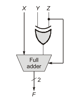
A full adder and an XOR gate are used to design a digital circuit with inputs X, Y, and Z, and output F, as shown below. The input Z is connected to the carry-in input of the full adder. If the input Z is set to logic ‘1', then the circuit functions as __________ with X and Y as inputs.