
A full adder and an XOR gate are used to design a digital circuit with inputs X, Y, and Z, and output F, as shown below. The input Z is connected to the carry-in input of the full adder. If the input Z is set to logic ‘1', then the circuit functions as __________ with X and Y as inputs.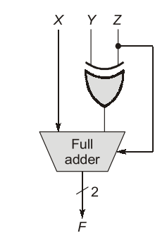
Let's analyze the digital circuit consisting of a full adder and an XOR gate, with inputs X, Y, and Z, and output F. The diagram shows that the input Z is connected to the carry-in input of the full adder.
Given that the input Z is set to logic '1', we need to determine how the circuit functions when X and Y are the inputs.
Step-by-step Analysis:
- The full adder takes inputs X, Y, and Z. Under normal circumstances, a full adder performs binary addition of these three inputs.
- An XOR gate is used prior to the full adder. It's known that XOR logic is used in digital circuits to perform bit inversion or bit-wise addition without carry.
- When Z = 1, an XOR gate inverts the input it processes. Thus, for the input Y, it becomes the inverse, i.e., \(Y' (Y \oplus 1)\).
- Now, the inputs to the full adder are X, \(Y'\), and Z = 1.
- The behavior of a full adder with these inputs can be evaluated as follows:
| X | Y | Z (Carry-in) | F (Sum) |
|---|---|---|---|
| 0 | 0 | 1 | 1 (because: \(0 \oplus 1 \oplus 1 = 1\)) |
| 0 | 1 | 1 | 0 (because: \(0 \oplus 0 \oplus 1 = 0\)) |
| 1 | 0 | 1 | 0 (because: \(1 \oplus 1 \oplus 1 = 0\)) |
| 1 | 1 | 1 | 1 (because: \(1 \oplus 0 \oplus 1 = 1\)) |
This truth table corresponds to the behavior of a subtractor. Specifically, the circuit is performing \(X - Y\) with Z set to 1.
Conclusion: When Z is set to logic '1', the circuit functions as a subtractor with X and Y as inputs.
Important Questions from Subtractors
In a half-subtractor circuit with X and Y as inputs, the Borrow (M) and Difference (N = X - Y) are given by


