
What logic function is implemented by the following circuit?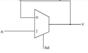
To determine the logic function implemented by the given circuit, we need to analyze the components and their connections.
In the given circuit diagram, we can see a multiplexer (MUX) being used. The output of the multiplexer is fed back to one of its data inputs. This feedback mechanism makes it a sequential circuit capable of storing a bit of information, similar to how a latch operates.
Let's examine the setup:
- The multiplexer has a select line labeled "Sel", a data input labeled "A", and a feedback loop to another input. This configuration allows the multiplexer to retain its previous state depending on the select line.
- When the "Sel" is at 1, the output "Y" follows the input "A".
- When "Sel" is at 0, the output "Y" feeds back into itself, maintaining its state irrespective of "A".
This setup resembles a Latch (specifically a level-triggered D-Latch), which utilizes feedback to store a bit of information and holds it as long as necessary until it's changed by the control input.
Conclusion: The correct answer is that the circuit implements a Latch, as it can store a bit and maintain its state using feedback and control from the select line.
Therefore, the given options:
- NOT gate: Incorrect, as a NOT gate inverts the input, which is not the function depicted here.
- AND gate: Incorrect, as an AND gate outputs true only if all inputs are true, which is not applicable here.
- Flip-flop: Incorrect, flip-flops operate on clock edges and are not same as latches.
- Latch: Correct, aligns with the functionality demonstrated by the circuit.
Important Questions from Multiplexer
The number of control lines in a multiplexer is 5, identify the MUX.
Number of control lines required for 16 to 1 multiplexer is _____
In a multiplexer, the number of input lines is ‘n’ and the number of select lines is ‘m’. Which of the following is correct?
________ is used to carry digital data on analog lines.
Consider the sentence below.
There is a country that borders both India and Pakistan.
Which of the following logical expressions express the above sentence correctly when the predicate Country(x) represents that x is a country and Borders(x, y) represents that the countries x and y share the border?


