
The diagram shown below shows the shearing force diagram for a beam. Which of the following is the CORRECT bending moment diagram for the above shear force diagram?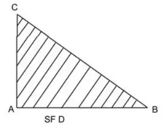
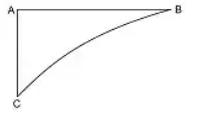
To solve this problem, we need to understand the relationship between the Shear Force Diagram (SFD) and the Bending Moment Diagram (BMD).
Key Concepts:
- A positive shear force indicates a clockwise moment, and a negative force indicates an anti-clockwise moment.
- The slope of the BMD is determined by the magnitude of the shear force. If the shear force is constant, the BMD is linear.
Given the shear force diagram, let's analyze how it impacts the bending moment diagram:
- From point A to B, the shear force is decreasing linearly from C to 0. This indicates that the bending moment will increase in a parabolic manner.
- The bending moment at any section is the area under the shear force diagram up to that section.
- Since the shear force diagram forms a triangle, the corresponding BMD should be a smooth curve starting from zero at A (as it is a free end) and reaching a maximum value at B, where the shear force transitions to zero.
Therefore, the correct bending moment diagram is a parabolic curve with the apex at the point where the shear force is zero.
Hence, the correct option is:
Important Questions from Shear Force and Bending Moment
For a simply supported beam of length L with a triangular load that varies gradually (linearly) from zero at both ends to w per unit length at the centre, the maximum bending moment is
For simply supported beams, the bending moment at supports (or ends) is always
A cantilever of length L carries a gradually (linearly) varying load from zero at its free end to w per unit length at the fixed end. The product of deflection and flexural rigidity at the free end is
If the shear force at a section of a simply supported beam is zero, the bending moment at the section is
Shear force at any point of the beam is the algebraic sum of


