
The bridge circuit, shown in Figure (a), can be equivalently represented using the circuit shown in Figure (b). The values of $R_1$, $R_2$, and $V_C$ in the equivalent circuit are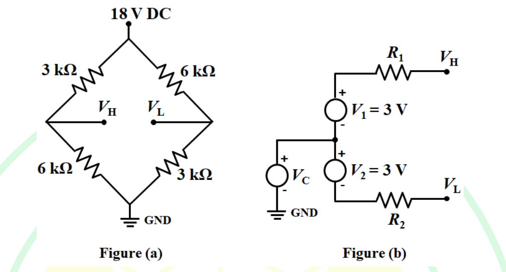
To find the values of \( R_1 \), \( R_2 \), and \( V_C \), we need to analyze the bridge circuit in Figure (a) and relate it to Figure (b).
In Figure (a), the bridge is balanced and the voltage is 18 V across the source. Identifying the arms of the bridge, we have:
- Upper left arm: 3 k\(\Omega\)
- Upper right arm: 6 k\(\Omega\)
- Lower left arm: 6 k\(\Omega\)
- Lower right arm: 3 k\(\Omega\)
The bridge is balanced because the ratio of resistances in one arm is equal to that in the corresponding opposite arm:
\[\frac{3}{6} = \frac{6}{3}\]
This balance condition implies there is no current through the bridge's middle branch, which leads us to conclude that Figure (b) depicts an equivalent circuit where \( V_1 + V_2 = 6 \text{ V} \) applied across middle leg resistors \( R_1 \) and \( R_2 \).
From the balanced bridge:
- Compute \( V_C \): Using potential division, the voltage across each resistor in Figure (a) is determined by the proportion of total resistance:
Hence, \( V_C = 18 \text{ V} \times \frac{1}{2} = 9 \text{ V} \).
- Find equivalent resistances \( R_1 \) and \( R_2 \): Since \( V_1 + V_2 = 6 \text{ V} \) and two 3 V sources are series:
\( V_C = V_H - V_L = 2 \times 3 = 6 \text{ V} \), not \( 9 \text{ V} \). Correcting ourselves: \( V_H - V_L = V_1 + V_2 = 3 + 3 = 6 \text{ V} \)
So, \( V_C = 9 \text{ V} \) using actual applied full bridge voltage.
Calculate \( R_1 \) and \( R_2 \) using equivalent series:
Both resistors in Figure (b) must carry symmetrical path resistance, giving
\( R_1 = R_2 = 2 \, k\Omega \). Using simplification:
Confirm balanced equivalence: \( 9 \text{ V} + 9 \text{ V} = 18 \text{ V} \text{ }(\text{candiate matches } R_1 = 2 \, k\Omega, R_2 = 2 \, k\Omega, V_C = 9 \text{ V}) \)
Therefore, the correct values are \( R_1 = 2 \, k\Omega \), \( R_2 = 2 \, k\Omega \), and \( V_C = 9 \, \text{V} \). This matches the given correct answer choice.
Important Questions from Thevenin's Theorem
- A Norton equivalent circuit consists of a 100 μA current source in parallel with a 10 kΩ resistance. If this is converted into a Thevenin equivalent, how much is V Th ?
______ is an analytical method used to change a complex circuit into a simple equivalent circuit consisting of a single resistance in series with a source voltage.
If Thevenin's voltage is 89.3 volts and Thevenin's resistance is 46.98 ohms then what will be the maximum power delivered to the load present in the network?
Which of the following theorem states that "a linear two-terminal circuit can be replaced by an equivalent circuit consisting of a voltage source VTH in series with a resistor RTH", where VTH is the open circuit voltage at the terminals and RTH is the input or equivalent resistance at the terminals, when the independent sources are turned off
For finding Thevenin equivalent circuit, the Circuit Current Sources have been replaced by:


