
The Voltage Source Inverter (VSI) shown in the figure below is switched to provide a 50 Hz, square-wave ac output voltage (vo) across an R-L load. Reference polarity of vo and reference direction of the output current io are indicated in the figure. It is given that R = 3 Ω, L = 55.9 mH.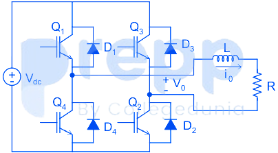
In the interval when v0 < 0 and i0 > 0 the pair of devices which conducts the load current i
D3, D4
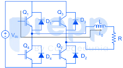
Case I: When Q1 and Q2 ON
In this case, the positive terminal of V0 will be at a higher voltage. i.e V0 > 0 and so i0 > 0 (i.e it will be positive).
Case II: When Q3, Q4 ON, and Q1, Q2 OFF
In this case, the negative terminal of applied voltage V0 will be at a higher potential i.e., V0 < 0, and since, inductor opposes the change in current so, although the polarity of Voltage is inversed, current remains the same in the inductor i.e., I0>0.
In this condition since, IGBT's can't conduct reverse currents, therefore, current will flow through D3, D4 until ID becomes zero.
Important Questions from Inverters
Output voltage wave shape of a basic series inverter is
The output of SMPS is ______.
Which one of the following controls reduce the size of the transformer in a switch mode AC power supply?
The rms value of load phase voltage is
If the dc bus voltage Vd = 300 V, the power consumed by 3-phase load is


