
In the circuit shown in the Figure, $A$ and $B$ are logic inputs and $Y$ is the logic output.
Which of the following logic operations is realized by the circuit?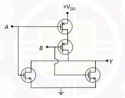
To determine the logic operation realized by the given circuit, let's analyze it step by step. The circuit comprises MOSFETs arranged to perform a logic function on the inputs \( A \) and \( B \), producing an output \( Y \).
Step-by-Step Analysis:
- The circuit shown is a NOR Gate. A NOR gate outputs a logic high only when all inputs are logic low.
- In the given circuit, two transistors are arranged in parallel connected between the input signals \( A \) and \( B \) and the ground. When \( A \) or \( B \) is high, these transistors conduct and pull the output \( Y \) to ground, making \( Y \) low.
- However, if both \( A \) and \( B \) are low, neither of the transistors conducts, leaving the output \( Y \) connected to \( +V_{DD} \) through the pull-up resistance, making \( Y \) high.
Truth Table Analysis:
| A | B | Y (Output) |
|---|---|---|
| 0 | 0 | 1 |
| 0 | 1 | 0 |
| 1 | 0 | 0 |
| 1 | 1 | 0 |
The truth table confirms that the circuit performs the NOR operation: output is high only when both inputs are low.
Conclusion: The correct answer is NOR as the circuit implements a NOR gate logic function.
Important Questions from Logic Gates
A two-input logic gate is giving high output only when both the inputs are high. For all other input conditions, the output is low. Select the correct logic gate.
The output is high only if one of the input is high. The above statement represents _____
The number of gate inputs, required to realize expression ABC + AB̅CD + EF̅ + AD is
Which of the following is logically equivalent?
A. ¬p → (q → r) and q → (p ∨ r)
B. (p → q) → r and p → (q → r)
C. (p → q) → (r → s) and (p → r) → (q → s)
Choose the correct answer from the options given below :
Consider the expression Y = P ⨁ Q ⨁ R where P, Q, R are the input variables and Y is the output variable. Y will be logic 0 if
(A) an odd number of input variables are 1
(B) an even number of input variables are 1
(C) an odd number of inputs variables are 0
(D) an even number of input variable are 0
(E) an odd number of input variable between 0 and 1
Choose the correct answer from the options given below:


