
Figure represents a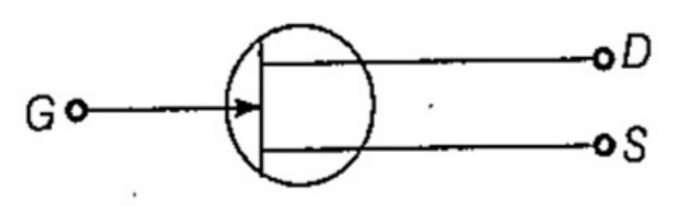
The given figure represents a semiconductor device. Let's identify the device based on the terminals and the symbol provided.
In the diagram:
- G stands for the Gate terminal.
- D stands for the Drain terminal.
- S stands for the Source terminal.
The symbol shown here is of a Junction Field Effect Transistor (JFET). A JFET is a type of Field Effect Transistor (FET) that controls the electrical current by using an electric field to control the shape and hence the conductivity of a channel of one type of charge carrier in a semiconductor material.
Let's evaluate each option to understand why it's not the correct choice:
- Zener Diode: This is used for voltage regulation and has a different symbol usually depicted with an angled Z at the cathode.
- Silicon Controlled Rectifier (SCR): This is usually a 3-terminal device but arranged with an anode, cathode, and gate, differing from the diagram shown.
- Tunnel Diode: Known for its tunneling effect and has a symbol different from what's shown in the image.
- Junction Field Effect Transistor (JFET): As explained above, the symbol matches a JFET, with these specific terminals (Gate, Drain, Source).
Conclusion: The correct answer is junction field effect transistor based on the symbol and terminal arrangement.
Important Questions from Diodes and Its Applications
Which of the following has superior bandwidth and temperature stability?
12 V DC and 24 V DC are general operating voltages for:
Which of the following diodes is a signal diode
A bridge type full wave rectifier requires-
Gunn diode is made of -


