
Consider the loaded beam as shown in the figure below.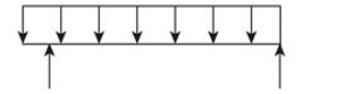
Choose the CORRECT option for the bending moment diagram of the beam above.
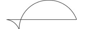
The question involves determining the correct bending moment diagram for the given beam under loading conditions.
To solve this problem, we need to analyze the beam and the loading on it. The beam is simply supported with both point loads and uniformly distributed loads (UDL).
Here are the steps to find the bending moment diagram:
- Identify the type of beam and loads: This is a simply supported beam with a combination of point loads and a UDL.
- Calculate reactions at supports: Use the equilibrium equations to calculate the reactions at the supports (taking moments about one support to find the reaction at the other support and vice versa).
- Draw the Shear Force Diagram (SFD): Start from one side of the beam, and calculate the shear force at each point of interest (usually at the point loads and at the ends of the UDL).
- Draw the Bending Moment Diagram (BMD): The bending moment at any section can be calculated by integrating the shear diagram. BMD is typically a linear function under point loads and a parabolic function under a UDL.
For a simply supported beam with a UDL in the middle, the bending moment diagram will typically have a triangular shape with the maximum moment located at the center of the beam.
Based on these calculations and understanding, we choose the appropriate bending moment diagram from the options provided. The correct option is shown below:
The chosen diagram correctly represents the bending moment characteristics of the loaded beam. The maximum bending moment occurs at the center, and the moments at the supports are zero, consistent with a simply supported beam.
Important Questions from Bending Moment
For a simply supported beam carrying distributed load w per unit length, consider the following relations between shear force F and bending moment M.
A. \(\rm w=-\frac{dF}{dx}\)
B. \(\rm w=-\frac{d^2M}{dx^2}\)
C. \(\rm F=\frac{dM}{dx}\)
Which of the above statements is/are correct ?
A simply supported beam of 4 m span carries a uniformly distributed load all over the span of 20 kN. The maximum bending moment is
When a beam is subjected to a bending moment, the strain in a layer is _____ the distance from the neutral axis.
- A cantilever and a simply supported beam have the same length and are subject to the same uniformly distributed load. The ratio of their maximum bending moments is
For a cantilever beam of length 2 m, under load of 1 kN/m, the maximum bending moment is


