
Consider a lossless transmission line terminated with a short circuit as shown in the figure below. As one moves towards the generator from the load, the normalized impedances $Z_{inA}$, $Z_{inB}$, $Z_{inC}$, and $Z_{inD}$ (indicated in the figure) are _____________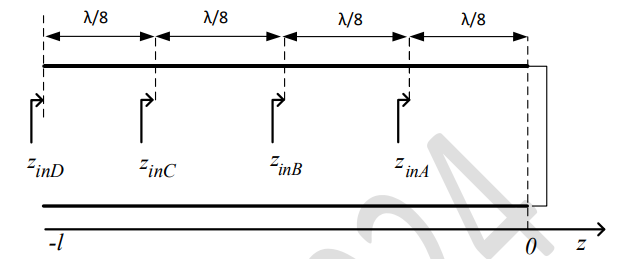
To solve this problem, we need to analyze a lossless transmission line terminated with a short circuit, and calculate the normalized impedance at different points as we move from the load towards the generator.
For a lossless transmission line terminated with a short circuit, we know that:
1. The input impedance of a short-circuited transmission line of length \(\lambda/8\) is given by:
\(Z_{in} = jZ_0 \tan(\beta \ell)\)
where \(\beta = \frac{2\pi}{\lambda}\) is the phase constant, \(\ell\) is the length of the line, and \(Z_0\) is the characteristic impedance.
2. Since the line is short-circuited:
At \(\ell = \lambda/8\), \(\tan(\beta \ell) = \tan(\pi/4) = 1\), so \(Z_{in} = jZ_0\)
At \(\ell = \lambda/4\), \(\tan(\beta \ell) = \tan(\pi/2) = \infty\), so \(Z_{in} = \infty\)
At \(\ell = 3\lambda/8\), \(\tan(\beta \ell) = \tan(3\pi/4) = -1\), so \(Z_{in} = -jZ_0\)
At \(\ell = \lambda/2\), \(\tan(\beta \ell) = \tan(\pi) = 0\), so \(Z_{in} = 0\)
Let's match these results with the points:
- \(Z_{inA} = +j\Omega\) (at \(\lambda/8\))
- \(Z_{inB} = \infty\) (at \(\lambda/4\))
- \(Z_{inC} = -j\Omega\) (at \(3\lambda/8\))
- \(Z_{inD} = 0\) (at \(\lambda/2\))
Hence, the correct answer is $Z_{inA}=+1j\Omega$, $Z_{inB}=\infty$, $Z_{inC}=-1j\Omega$, $Z_{inD}=0$.
Important Questions from Transmission Lines
A characteristic impedance does NOT satisfy which of the following statements?
Twisting of live and return lines in long signal lines is done to reduce the effect of
A transmission line of \(50{\rm{\;\Omega }}\) characteristic impedance is terminated with a \(\rm 100 \ Ω\) resistance. The minimum impedance measured on the line is equal to
For transmission line load matching over a range of frequencies, it is best to use a
Inductance and capacitance per unit length of a lossless transmission line are 250 nH/m and 0.1 nF/m respectively. The velocity of the wave propagation and characteristic impedance of the transmission line are respectively


