
A 3-bit DAC is implemented using ideal opamp and switches as shown in the figure. Each of the switches gets closed when its corresponding digital input is at logic 1. For a digital input of 110, the resistance $R_{in}$ seen from the reference source and the current $I$, are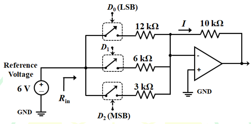
The given problem involves a 3-bit Digital-to-Analog Converter (DAC) using an op-amp and switches, with input represented as a binary number. The task is to determine the input resistance \(R_{in}\) and the current \(I\) for the digital input "110".
- Identify Binary Digits for the Input "110":
- \(D_2 = 1\)
- \(D_1 = 1\)
- \(D_0 = 0\)
- Connect the Corresponding Resistors:
- \(3 \, \text{k}\Omega\) and \(6 \, \text{k}\Omega\) are connected since \(D_2\) and \(D_1\) are '1'.
- Calculate the Equivalent Resistance:
- Using parallel resistance formula: \(\frac{1}{R_{eq}} = \frac{1}{3} + \frac{1}{6} \, \text{k}\Omega\)
- \(R_{eq} = 2 \, \text{k}\Omega\)
- Determine the Total Current \(I\):
- Using Ohm's law: \(I = \frac{V}{R_{eq}} = \frac{6}{2} = 3 \, \text{mA}\)
- Conclusion:
- The input resistance \(R_{in}\) seen from the reference source is \(2 \, \text{k}\Omega\).
- The current \(I\) is \(3 \, \text{mA}\).
Therefore, the correct answer is
\(R_{in} = 2 \, \text{k}\Omega\) and \(I = 3 \, \text{mA}\)
.
Important Questions from Digital To Analog Converters
A D/A converter has 5V full-scale input voltage and an accuracy of ± 0.2%. The maximum error for any output voltage will be
An ideal 6-bit DAC with zero offset gives output voltage of 0.1 V for an input ‘000010’. What is the output for input ‘001010'
Identify the most significant bit from the '100010' binary data.
Two 10-bit ADCs, one of successive approximation type and other of single slope integrating type, take Ta and Tb time respectively to convert 3V analog input signal to digital output. If the input analog signal is increased to 6V, the approximate time taken by the two ADCs will respectively be
The resolution of $4\frac{1}{2}$-digit voltmeter is:


